 |  |
| |
This document describes how to build a simple and inexpensive wearable RFID reader. The entire hardware configuration is attached to the user's forearm and the RFID tags are read by an antenna fitted into the palm of a padded glove (see Figure 1). We believe that this construction is best suited for rapidly prototyping systems. More robust (but also more complicated and expensive) systems are described in [1] and [2].
Please read this entire document before purchasing any components or materials.
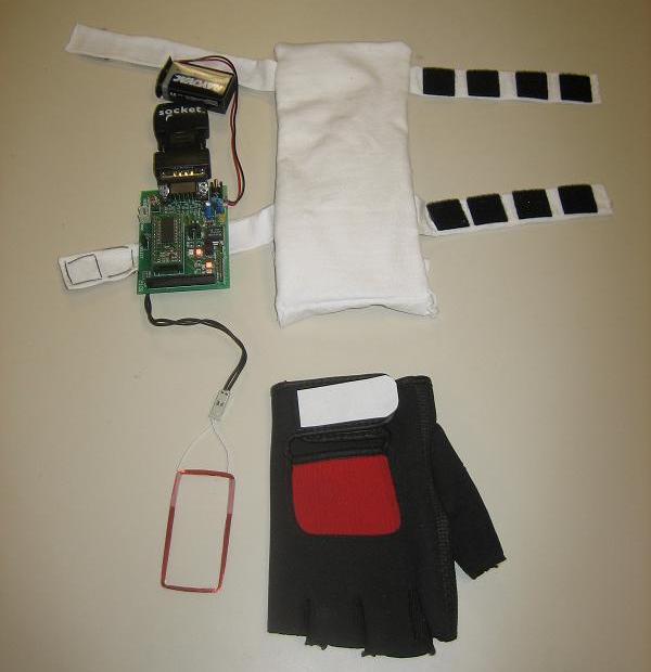
Figure 1. Wearable RFID reader
The next section (Section 2) describes how to set up the hardware for the device (some soldering is required). Section 3 describes how to wirelessly read data from the device. Section 4 describes how to sew a wearable enclosure for the device. Section 5 describes a simple RFID-tagged game board that can be built to use with the device.
The wearable RFID reader described in the next three sections is built using:
 SonMicro SM125-EK RFID Development Kit |
 Socket Cordless Serial Adapter |
 9V Battery |
The described device reads 125 kHz RFID tags. We have used 30mm global EM4102 tags from Trossen Robotics, but all commonly available 125 kHz tags should work. Please note that high-frequency (13.56 MHz) or ulta-high frequency tags will not work with this reader.
You will also need a soldering iron and some basic soldering skills. We describe how to sew a wearable enclosure for the RFID reader, but such an enclosure can potentially be built in any number of different ways.
The Socket Cordless Serial module is one of a number of commercially available devices that can send serial port data over Bluetooth. We have found that the Socket is a good trade-off between price and quality. We have tried the less expensive AIRCable Serial, but it was buggy and didn't maintain a Bluetooth connection well. Other (usually more expensive) devices can offer a smaller form factor or provide a longer range of operation. Some considerations to make when choosing a device are: (1) whether it can be powered through the serial port; (2) whether it has a class 1 radio (which provides a long range, but is also more power-hungry) or a class 2 radio (which provides a shorter range, but uses less power); and (3) whether it expects the connecting device to perform hardware flow control. These issues are further explained below.
The SonMicro RFID reader is a 125 kHz RFID reader. The development kit it comes in includes two RFID antennas -- we have used the smaller one, as it is possible to fit it into the palm of a padded glove.
The Socket Cordless Serial Adapter connects to the RFID reader's serial port and allows us to read and write to it over a Bluetooth connection. It has a class 2 Bluetooth radio with a range of approximately 10 meters (30 feet). The device can be powered through pin 9 of its serial port connector and takes a fairly wide range of DC voltage.
The RFID reader's antenna fits awkwardly into a socket on its board, so the first step in building the wearable RFID device is to extend the reader's antenna. First, cut off the tall, excess plastic from the site where the antenna connects to the board. Then solder two thick, pliable lengths of wire under the socket (see Figure 2). The wires should fit snugly into the two holes of the connector on the antenna itself. Make the wires long enough to allow the RFID reader board to sit on a person's forearm and the antenna to be on the user's palm (but not so long that they can easily snag on something or get in the user's way).
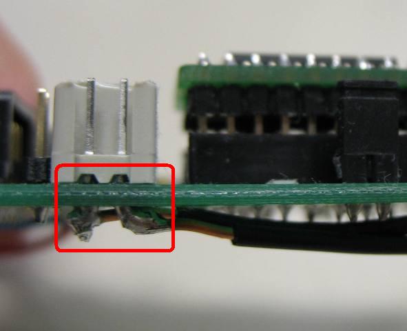
Figure 2. Close-up of the antenna extension.
The thin wires leading off the antennas shipped with the SonMicro Development kit are very fragile. It is a good idea to secure them so that they cannot be broken or pulled off the antenna loop.
The antenna loop itself is also not flexible. We have found that it works fine for our purposes when inserted into a padded glove, but it may not work in situations requiring more dexterous hand and palm motion. While creating a custom, flexible antenna loop is technically possible, it would need to be impedance-matched to the SonMicro RFID reader's electronics. This is an issue outside the scope of this how-to.
The Socket Cordless Serial Adapter expects the device it is connected to to perform CTS/RTS hardware flow control. Flow control helps devices negotiate data exchange -- a brief description is provided here. Unfortunately, the SonMicro doesn't perform any sort of flow control.
Luckily, simulating CTS/RTS flow control is as easy as soldering together the CTS and RTS pins on the SonMicro RFID reader's serial connector. Place a dab of solder between pins 7 and 8, as shown in Figure 3. Now, whenever the Socket Adapter sends a RTS, it will immediately receive a CTS back.
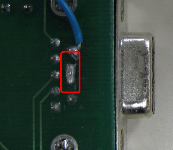
Figure 3. Pin 7 and pin 8 soldered together. (The wire coming off pin 9 will be explained in the next section.)
This setup has worked well for us. In some cases, however, it may lead to data loss or buffer overflows if the RFID reader cannot process data quickly enough to keep up with the data that is being sent from the Socket. Please consult the Tech Note by Socket on this issue.
It is possible to power the SonMicro RFID reader and the Socket Cordless Serial Adapter together off a single 9V battery. The Socket device expects power on pin 9 of its serial connector and can take a fairly wide range of DC voltage. Thus, it is necessary to solder a wire from the positive terminal of the 9V battery holder on the RFID reader to pin 9 of its serial connector (see Figure 4).
WARNING: Make sure to read section 3.1 before making this modification. Once this modification is made, voltage will be emitted from pin 9 of the SonMicro's serial connector anytime it is powered on (including if it is powered from the wall). Do not plug the SonMicro into any device that you are not sure can handle the voltage (e.g. a desktop or laptop computer).
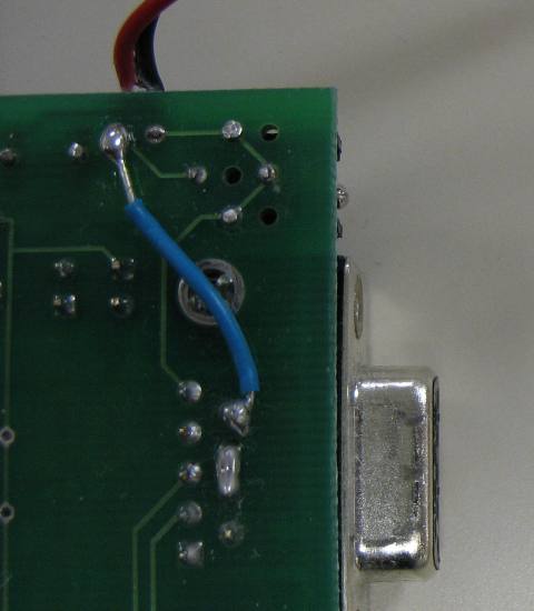
Figure 4. Pin 9 is connected to the positive battery terminal.
We have found that our device works for about 1 hour with the SonMicro RFID reader in full power, continuous read mode (described in the next section). We found that in our setup the device draws about 90 mA when just powered on, and about 115 mA when connected over Bluetooth and reading RFID tags. Once the battery reaches approximately 8.5V, the Socket adapter starts dropping Bluetooth connections. It may be possible to extend battery life either by putting in two 9V batteries in parallel (at the expense of extra weight) or by using a more intelligent tag-reading profile.
Below, we give Python and C source code that can be used to connect to the device constructed in Section 2. The Python code uses the PyBluez module and should work both under Linux and Windows XP. The C code will only work under Linux, and requires the BlueZ Bluetooth stack and libraries.
Before you run the code, you will need to edit the file and change the Bluetooth address to the address of your Socket Cordless Adapter (find this using the utility included with it). If you are using different read settings on the SonMicro RFID reader, you will also need to change the first line of the read command that is sent to put the device into read mode (explained below). After that, compile the code (if using the C sources), power on the wearable RFID setup, and run the program. It should connect automatically and start displaying the IDs of the RFID tags that are detected by the reader.
	Python source code

	C source code
Using the SMRFID program (comes with the SM125-EM kit; or download here) it is possible to determine what read settings will allow the SonMicro RFID reader to detect your tags. To read our tags (30mm global EM4102 tags from Trossen Robotics) we set Modulation Type to "Manchester RF/64", # of Blocks to 1, and use the "EM4100/02 (decoded)" mode. These settings should work for most common tags. NOTE: You should do this before you make the modification described in Section 2.3!
The SonMicro RFID reader is initialized by sending it a read command and a request for acknowledgement of the command. If you are using the same settings as we are [Manchester RF/64, 1 Block, Full Power, EM4100/01 (decoded)] the hexadecimal codes for setting the device into continuous read mode are:
	0x72 0x65 0x33 0x36 0x34 0x02 0x07 0x01 (read command)

	0x61 0x63 0x6B 0x6E 0x77 0x6C 0x67 0x65 ('acknwlge' request)
If you need to use different settings, you will have to intercept the codes using a serial line monitoring utility. We use a Keyspan USB Serial Adapter, which includes a simple monitoring utility. Send the read command from SMRFID and watch for the read code and the 'acknwlge' code. The reader will echo them back and follow up with an 'acknokok'. After this, it will start sending back any detected RFID tags as 10-digit hexadecimal numbers (in ASCII). You will also need to sniff the codes if you want to use a different tag-reading profile (i.e. non-continuous reading). We have not been able to find any documentation on the SonMicro support website about the codes the RFID reader understands.
Using the utility included with it, you need to set up the Socket Cordless Serial Adapter to receive data from the RFID reader and communicate over Bluetooth. First, its mode needs to be Acceptor. Then, in the Properties dialog, in the Connections tab, make it "Connectable and Discoverable" (discoverability is optional, but we found that it makes working with the device easier). In the Port Settings tab, select 19200 bits per second, 8 data bits, NONE parity, and 1 stop bit. Write these settings to the adapter.
We recommend using the PyBluez Python module to connect to the Socket Cordless Adapter over Bluetooth. This document gives a good overview of how to setup Bluetooth connections using BlueZ and PyBluez, under Linux. PyBluez works for both Windows XP and Linux, however, so the operating system shouldn't matter for the sections of the document that explain PyBluez.
In the code given above, we setup a RFCOMM connection on port 1, with no pairing or PIN code.
To make the RFID device wearable, we suggest embedding the RFID antenna into the palm of a workout glove and housing the RFID reader, 9V battery, and Socket module into a sewn cloth encasing. We were able to find a workout glove with a piece of sewn padding on the palm side of the glove, which we slit open to form a slit in which to place the RFID antenna (see Figure 5).
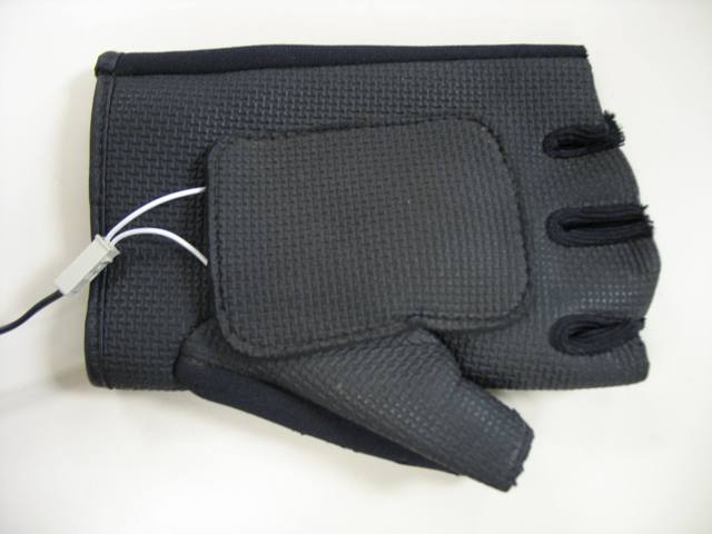
Figure 5. RFID antenna inserted into the palm of an old glove.
There are a number of different encasings that can be made to fit the remaining hardware for the RFID device. We describe the specific design which we used for the encasing of our wearable device. In addition, while it is possible to sew this encasing by hand (our encasing was hand-sewn), an identical encasing can also be made using a sewing machine, which would save a substantial amount of time. Our cloth encasing is made from 100% white cotton fabric (cut from an old T-shirt) and Velcro squares (which can be purchased at an office supply store or fabric store). In addition, our encasing is double-layered, with pouches on the top and bottom which can be lined with cotton to make the encasing feel more comfortable for the wearer (see [3] for more on design for wearability). The encasing has a Velcro flap at the front to secure the electronics inside. Two Velcro straps on each side of the encasing are used to strap the encasing around the wearer's forearm.
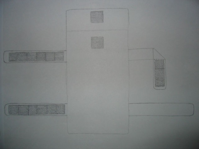
Figure 6. Sketch of the wearable enclosure.
First, cut eight 1 by 6.5 inch strips of fabric. The strips of fabric can also be cut wider -- the important detail is that they should be at least 1/4 inch wider than the width of the Velcro being used. Take two strips at a time and sew them together by aligning the two strips atop one another and sewing about 1/8 inch from the edges along both long sides of the fabric and only one of the shorter sides. This will leave you with four sewn together pairs of strips, or straps, each with one open end. Carefully turn these straps inside out so that the sewn seams are now concealed on the inside. You may also want to take a pen (or a small rod or similar object) and poke the corners on the inside of each strap to better define the edges.
Now, take some Velcro squares and glue them (using sturdy fabric glue) side by side onto each strap, starting from the sewn edge and leaving about 1 inch of fabric left on the unfinished edge. Glue the Velcro squares such that two of the four straps have one side of the Velcro on them and the other two have the other side of the Velcro (one side of the Velcro is stiffer and loopy while the other side is softer). Wait for the Velcro squares to set in the glue before working with the straps (depending on the glue used, it may be necessary to let the glue set overnight). Alternatively, you can also sew the Velcro to the straps, though this requires sewing them to four of the original eight fabric strips before pairing the strips and sewing them together. In this case, pair a strip that has Velcro sewn on it with one that does not. Please note that Velcro is sturdy and hard, making it a difficult material to sew through, even when using a sewing machine.
Cut three 8.5 by 4.5 rectangles of fabric and one 10 by 4.5 rectangle of fabric. Align the four pieces of fabric atop one another, placing the longer piece on the bottom and making sure the pieces are flush along the bottom edge. Along the left edges, in between the second and third piece of fabric from the topmost piece and about 1 inch from the shorter edge, pin one of the four Velcro strips (Velcro-side up) such that the unfinished edge is aligned with the edge of the rectangular pieces of fabric. About 4.5 inches below this piece, pin a second Velcro strip in a similar fashion. Make sure that this second Velcro strip contains the same side of the Velcro as the first strip. Now, pin the remaining two Velcro strips (containing the other side of the Velcro) to the other edge of the fabric (Velcro-side down), in the exact same locations from the shorter edge as the first two strips.
In a similar fashion as with the Velcro strips described above, sew 1/4 inch from the edges along the left, right, and bottom edges of the fabric. Leave the top edge unfinished, as the extra fabric from the longer piece of fabric will be used to make the Velcro flap. Carefully remove the pins placed previously to secure the Velcro strips during sewing, and turn the sewn fabric inside out so that the Velcro straps are on the outside and the longer piece of fabric is on the bottom. Glue or sew a square of Velcro centered and flush along the top edge of this extra length of fabric. Finally, glue or sew a square of Velcro of the same size (this time using the other side of the Velcro) centered on the top piece of fabric, so that it aligns with the piece on the flap when the flap is closed.
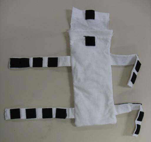
Figure 7. The finished wearable enclosure.
Take some cotton (you can pull apart cotton balls) and stuff them in between the pieces of fabric, where the pouches are. Now, place the wearable SonMicro reader into the main pouch of the fabric encasing, making sure the 9V battery and Socket module go in first. Leave the antenna outside the encasing, and close the flap. Insert the RFID antenna into a workout glove. You now have a wearable RFID device that is ready for the user to try on!
To test our device, we constructed a simple game board from a piece of 28 by 22 inch posterboard, some colored construction paper, and 20 RFID tags. The board contains 20 colored circles (4 circles of each of 5 colors) arranged in a 5x4 configuration. The circles are 4 inches in diameter and spaced 1.5 inches apart from each other. We placed 20 round RFID tags on the backside of the posterboard, at the center of every colored circle located on the front side of the posterboard. Figure 8 shows the completed board.
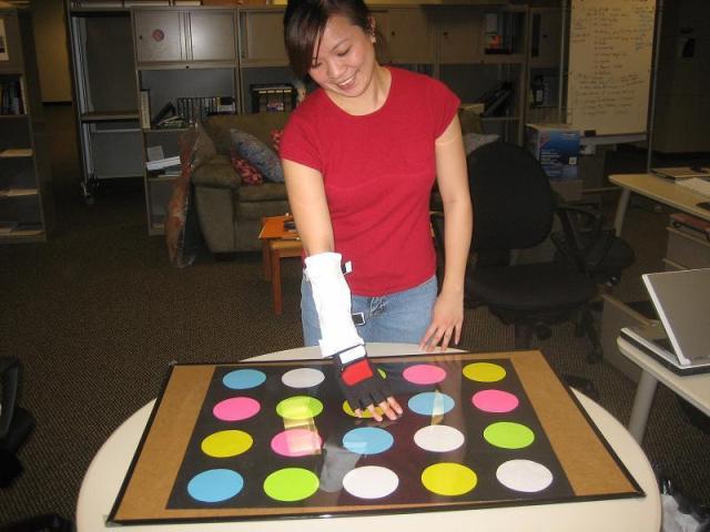
Figure 8. Susan wearing the device and interacting with the game board.
Using this setup, we created a two-player, proof-of-concept game with which we tested two wearable RFID readers. An advantage of wearable RFID technology which we highlight is the ease of prototyping and experimenting with different game designs using inexpensive and easily available materials. With RFID tags, it is possible to construct new game pieces out of existing game pieces (such as chess pieces or Tonka trucks) or even tag objects such as body parts [4] or furniture [5].
Some final notes: