Contextual Computing Group
PIC
The PIC HOWTO
Kent Lyons
Original a HOWTO
for Ubicomp Spring 00
This document is aimed at getting you
up and running with the setup in the FCLab for the PIC
micro-controllers including the types of PICs in the lab, and how to
program them with the lab equipment.
1. Introduction
This HOWTO gives a basic overview of the type of PICs that are
available and what we normally have in the lab. It describes the
development environment in the lab and how to use the hardware for
programming and erasing PICs. It also gives an overview on the special
aspects of the C compiler we use for the PICs. Finally there is a
simple program showing the basics needed for a simple application.
This HOWTO assumes the reader knows C. It would help to have some
background knowledge of micro-controllers. This howto does not
describe what to do with the PIC once you program it and doesn't
describe how to build circuits with the PIC.
2. PIC
The PIC micro-controller is made by Microchip. There are lots of
different flavors that have features ranging over the amount of RAM,
program ROM, the type of ROM used (EPROM, EEPROM), and the types and
numbers of onboard peripherals such as UARTs for serial, timers, and
analog to digital converters.
The PICs we normally have in the lab are the PIC16C77 and
PIC16F84.
2.1 16C77
The PIC16C77 (Datasheet)
comes in several packages. We have the 40 pin PDIP for easy
prototyping in breadboards. It has 8192x14 words of program memory and
368x8 bytes of data ram, a max speed of 20MHz, 33 digital I/O ports 8
8-bit ADC, serial I/O hardware for USART, I2C, and SPI. 2 Pulse width
modulators, brown out detection, 3 timers + the watchdog timers. The
program data is stored in EPROM so to reprogram the PIC it needs to be
erased with the UV eraser. This PIC pretty much has a little bit of
everything and lots of memory and I/O. This makes it rather easy to
prototype when you don't know exactly what you need.
Picture of a 16c77. Pin 1 is on the left.
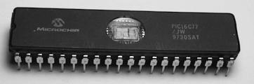
The pinout for the 16c77
2.2 16F84
The PIC16F84 (Datasheet)
also comes in several packages and we have the 18 pin PDIP. This PIC
has 1024x14 words of program memory and 68x8 bytes of data ram. It has
a max speed of 10 MHz (20MHz for the 16F84a) 13 digital I/O ports, 1
timer and the watchdog timer. It has much less than the '77 but is
smaller and uses less power. This PIC uses flash memory to store the
program instead of EPROM. As a result you do not have to erase it with
the UV eraser. The PIC programmer clears the PIC when it is
reprogrammed.
Although this PIC does not have the hardware to
support a serial connection the C compiler we have has functions to
emulate the serial hardware in software.
Picture of a 16f84. Pin 1 is on the left.
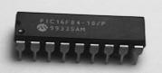
The pinout for the 16f84
3. The Lab Setup
3.1 The PIC Station
In the FCLab we have a Win95 laptop setup to program the PIC
micro-controllers. It has Microchip's MPLab development software and
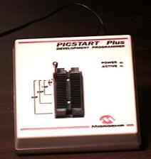
the CCS PIC C compiler. The laptop is connected to a PICSTART Plus
programmer (we currently have 3 programmers total).
The PIC station
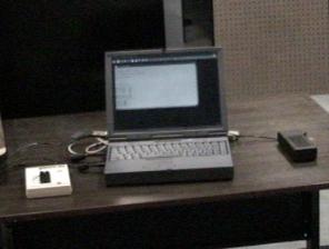
The PICSTART Plus programmer is attached to the serial port of the
laptop.
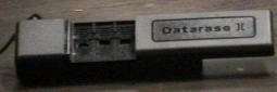
Near the laptop is also the UV eraser. This device has an ultra-violet
light that clears EPROMs and is the device used to erase the
PC16C77.
3.2 Other Lab Resources
We also have
all of the basic support hardware to get the PICs up and running. This
includes 5 volt regulators, crystals, and lots of LEDs. We also have
the hardware needed to get the PIC to talk to a 'normal' PC rs232
serial port. We also have other random parts, but any other hardware
that you need for your project would probably need to be ordered.
4. The Programming Environment
MPLAB is an IDE supplied by Microchip that supports plug in compilers
and talks to the PIC programmer. It has a built in editor, talks to
the compiler and lets you program your PIC.
4.1 Making a new Project
Projects are
used to keep files together and store the settings (like what chip you
are using) together.
Important note: In order to keep all of your files together and
to prevent someone from accidently erasing/moving your files keep all
of your PIC related projects and code in the c:\pic-code directory on
the laptop. In that directory make a new subdirectory with your
name. For example the dir c:\pic-code\kent has all of my files in
it.
The step by step process to create a project:
This may seem kind
of ugly but I have tried to be as explicit as possible in describing
the steps needed to make a new project because some of the steps are
very non-intuitive.
To make a new project choose the menu 'Project', and then 'New
Project' That pops up a dialog asking for a new project name. Go to
the correct directory (c:\pic-code\foo\bar) and give it name. This
must be of the 8.3 dos filename convention.
The 'Edit Project' dialog box appears next.
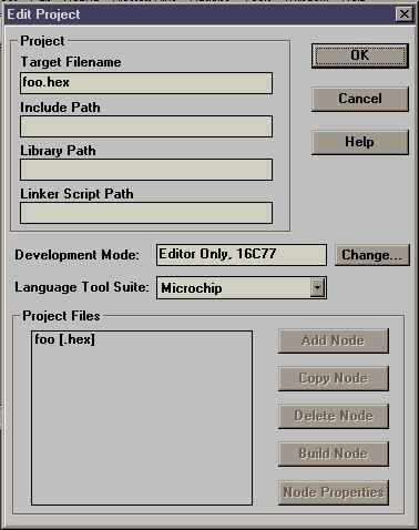
The processor for the project is
listed under 'Development Mode'. To select a different processor press
the 'Change...' button.
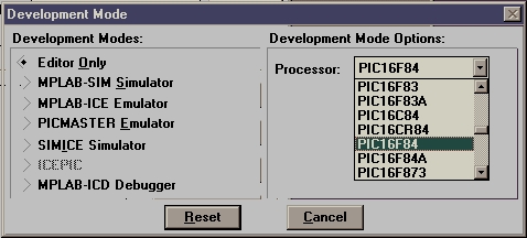
In the dialog box leave the 'Development Modes' as 'Editor Only' and
use the 'Processor' combo box to select the micro-controller you are
using for your project (PIC16F84, PIC16C77, etc). Once you have the
correct processor push the 'Reset' button.
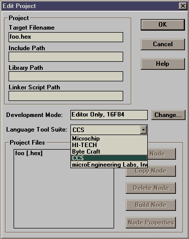
Next select the 'Language Tool Suite'. This chooses the compiler to
use. For this HOWTO I am going to assume the CCS compiler is used. So,
in the combo box select the 'CCS' option.
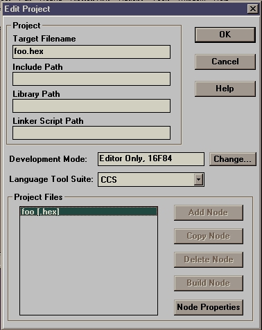
Now comes the strange part, adding a source code file to the
project. In the 'Project Files' list box click on the line that says
'foo [.hex]' where foo is your project name. Once that happens, the
'Node Properties' button becomes active.
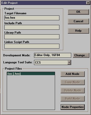
Push the 'Node Properties' button. That pops up a dialog. On that
dialog push 'OK'. Now back on the 'Edit Project' dialog the 'Add Node'
button is now enabled.
Push the 'Add Node' button and use the dialog box to select your
source code file. Push 'OK'. And push 'OK' again on the 'Edit Project'
dialog and you are done.
You now have a new project with a source code file in it. The first
thing you probably should do is save the project. To do so select the
'Project' menu and then 'Save Project'. If for some reason you need
to change any of those options latter (or in an existing project) you
can get to them through 'Edit Project' on the 'Project' menu. You
would need to do this if, for instance, you decided to use a different
micro-controller.
4.2 Programming a PIC
Using MPLAB to
program your PIC:
Luckily programming your PIC is much easier than
creating a project.
To compile your project select 'Make Project' from the 'Project'
menu.
This will pop up a window listing errors if there are
any.
Once your code has been successfully compiled you are ready to put it
on the PIC. Select 'Enable Programmer' for the 'Picstart Plus'
menu.
This will show an error dialog if the programmer is off or not
connected to the serial port.
If there is no error 2 dialogs will appear, 'PICSTART Plus Device
Programmer' and 'Configuration Bits'.
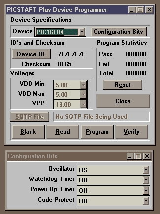
At this point insert the PIC you
wish to program into the programmer. Make sure pin 1 is at the top
(lever side) of the programmer!
In the 'PICSTART Plus Device Programmer' dialog make sure that the
Device is correct. Also make sure that the 'Configuration Bits' match
what you have in your program.
'Program' downloads the code into
the PIC.
'Blank' verifies that the PIC is blank.
'Read'
retrieves the code from a programmed PIC.
'Verify' makes sure the
code on the PIC is correct.
While the code is being transfered a status dialog will be shown
counting through the program memory.
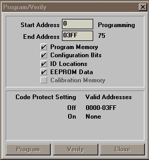
This dialog also warns if
there were any errors in the programming process.
5. The PIC C compiler
The C compiler
we have is made by Custom Computer
Services (CCS). They have a rather good compiler (info here) but their
documentation is lacking. This next section tries to make up for
that. A good chunk of the following info on the built in functions and
directives came from the help built into the compiler. Hopefully this
document explains things a little better and it is in a much better
format. :) How to get to the raw help is at the end of this
section.
5.1 Preprocessor Directives
#fuses
This directive sets the configuration for the
processor. For the processors we typically use (the 16F84 and 16C77)
it has options to select the type of clock (LP, XT, HS, RC), if the
watchdog time should be used (NOWDT, WDT), if the power up timer
should be used (NOPUT, PUT) and if the code should be protected
(PROTECT, NOPROTECT). The 16C77 also has the option to use brownout
(NOBROWNOUT, BROWNOUT) and extra code protection options (PROTECT_75%
and PROTECT_50%).
ALWAYS use NOPROTECT!!! Protecting the device burns out a fuse on the
IC and wont let you reprogram the chip, EVER.
The string I usually use and the one you probably should use unless
you know what you are doing is: #fuses HS,NOWDT,NOPROTECT,PUT This
uses a high speed xtal (the type we have), no watchdog, no code
protect, and waits to make sure the device is powered up before
starting to execute code.
Interrupts
The next batch of directives specify a function
as an interrupt function. An interrupt function may not have any
parameters and all local variables are automatically made static. An
interrupt function may not call a separate function. When the
interrupt is triggered, the function will get called. #INT_EXT
#INT_RTCC #INT_RB #INT_AD #INT_EEPROM #INT_TIMER1 #INT_TIMER2
#INT_CCP1 #INT_CCP2 #INT_SSP #INT_PSP #INT_TBE #INT_RDA #INT_COMP
I/O directives
#use STANDARD_IO
The compiler will
generate code to make the I/O pin either input or output every time
it is used.
Example: #use standard_io(A)
#use FAST_IO
This will cause the compiler to perform I/O without
programming the direction register. Use set_tris_X() to set the
direction for port X where X can be a, b or c
Example: #use
FAST_IO(A)
#use FIXED_IO
The compiler generates code to set the I/O pin for
input or output each time it is used. However, unlike STANDARD_IO, the
pins are programmed according to the directive, not how they are
actually used. (This saves a byte of ram per port compared to standard
I/O).
Example: #use FIXED_IO(a_outputs=PIN_A2,PIN_A3)
#use DELAY
This tells the compiler the speed of the
processor and enables the use of the built in functions DELAY_MS and
DELAY_US
Example: #use DELAY(clock=10000000) // 10MHz clock
#use RS232
This directive tells the compiler the baudrate
and pins to use for serial I/O. The USE DELAY directive must appear
before this directive can be used. This enables the built in in
functions GETCH and PUTCHAR to be used. The directive can have an
optional RESTART_WDT that would cause GETC() to clear the WDT as it
waits for input. The polarity of the pins can be inverted with
INVERT. This is can be useful when connecting to another TTL level
serial device. Parity can be set with PARITY=x where x is N, E, or O.
If the micro-controller has a built in UART and the pins specified
correspond to the UART then it will be used. (However, the INVERT
option does not work in this case). If there is no UART the compiler
will generate code to emulate the UART. If the baud rate can not be
generated within 3% of the desired value using the current clock an
error will be generated.
Examples:
#use rs232(baud=2400,
xmit=PIN_A1, rcv=PIN_A2)
#use rs232(baud=9600, xmit=PIN_B2,
INVERT, PARITY=O)
#BIT
This directive creates an id that may be used as a
short int (one bit). The id will reference an object at memory
location x with the bit offset y. x may be a constant or another
identifier, y must be a constant.
#BYTE
This directive creates an id that may be used as a
int (one byte). The id will reference an object at memory location
x. x must be a constant.
5.2 Built-in Functions
delay_us(time)
This will cause the program to wait 'time'
microseconds. Where time is a constant it can be 0-65025. Variable
delays can be 0-255. The 'use delay' directive must be used before
this function can be used so the compiler knows the clock speed.
delay_ms(time)
This will cause the program to wait 'time'
milliseconds. Where time is a constant it can be 0-65535. Variable
delays can be 0-255. The 'use delay' directive must be used before
this function can be used so the compiler knows the clock speed.
delay_cycles(count)
This will create a delay of 'count'
instruction cycles. 1 instruction cluck is 4 oscillator
clocks. delay_cycles(1) is the same as a NOP
sleep()
Issues the sleep instruction
restart_cause()
This function returns the reason for the last
processor reset. It will return one of: WDT_FROM_SLEEP, WDT_TIME_OUT,
MCLR_FROM_SLEEP, NORMAL_POWER_UP
restart_wdt()
This function will restart the watchdog timer. If
the watchdog timer is enabled, this function must be called
periodically to prevent the processor from reseting
output_low(pin)
output_high(pin)
These set the output pin
'pin' low/high
output_float(pin)
This sets the specified pin to input mode. This
allows the pin to float high on an open collector type of
connection.
output_bit(pin, value)
This sets the given pin to the given
value
input(pin)
This function returns the state of the given pin
set_tris_X(value)
X can be a, b, c, d or e This function allows a
tri-state register to be written to directly. This must be used with
the FAST_IO directive. Each bit in value represents a pin. 1 indicates
the pin is input, 0 is for output.
Example:
set_tris_e(0x00);
// set all of port e's pins to be output
putchar(val)
This function sends a character over the rs232 xmit
pin. The 'USE RS232' directive must appear before this call to
determine the baud rate and pin to use.
getch()
This function gets a character over the rs232 rcv pin. The
'USE RS232' directive must appear before this call to determine the
baud rate and pin to use.
kbhit()
This function returns true if the start bit of a character
is being sent on the rs232 rcv pin. The 'USE RS232' directive must
appear before this call to determine the baud rate and pin to use.
enable_interrupts(level)
disable_interrupts(level)
These
functions enable/disable interrupts for the given level. To use an
interrupt, a function must have been declared to handle that interrupt
with the correct INT directive. The interrupt levels are: GLOBAL,
ADC_DONE, RTCC_ZERO, RB_CHANGE, EXT_INT, INT_TIMER1, INT_TIMER2,
INT_CCP1, INT_CCP2, INT_SSP, INT_PSP, INT_RDA, INT_TBE
Example:
disable_interrupts(GLOBAL); // turn off all
interrupts
enable_interrupts(EXT_INT); // setup external interrupt call
enable_interrupts(GLOBAL); // activate all interrupts that have been
setup
5.3 Other Information
There are lots
of other built in functions and directives, but these should be enough
to get you started. Most of the other functions/directives are to
setup & use a specific piece of hardware like I2C or the timers.
To get to the (really bad) help that is built into the compiler run
c:\picc\pcm.exe Then use the online help, if you can...
The compiler is installed in c:\picc and c:\picc\examples has all of
the header files for the supported PICs and some example source
code.
6. An Example
blinky.c:
The following program flashes a
LED
#include <16F84.H> // I am using this PIC

// high speed xtal, no watchdog, no code protect, and use power up timer
#fuses HS,NOWDT,NOPROTECT,PUT

// tell compiler clock is 10MHz.  This is required for DELAY_MS()
// and for serial I/O, all of which use software delay loops.
#use DELAY(clock=10000000)

// declare that we'll manually establish the data direction of
// each I/O pin on port B.  #use fast_io(B) #define IRX_B_TRIS 0b00110000
// setup directions

// make a def for easy reference to the right pin
#define RED_LED PIN_B2
// (output) Red LED (low true)

// Macros to simplify I/O operations
#define RED_LED_ON output_low(RED_LED)
#define RED_LED_OFF output_high(RED_LED)


// blink the LED on for 'on' ms, then off for 'off' ms 'x' times void
blink(int on, int off, int x) {
  int i;
  for (i=0; i < x; i++) {
    RED_LED_ON; // turn on led
    delay_ms(on); // wait
    RED_LED_OFF; // turn of led
    delay_ms(off); // wait
  }
}

void main() {
// we want to use fast I/O so need to specify direction for pins
set_tris_b(IRX_B_TRIS);

  while (1) { // forever
    blink(250, 125, 5); // blink
   delay_ms(250); // wait a while
  }
}
The hardware that runs this program is rather simple
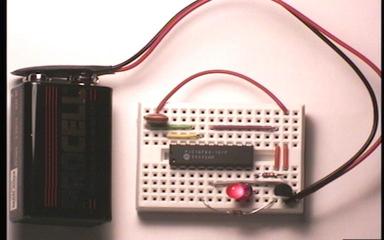
At the heart of this is a PIC16F84
(pin 1 is to the left)
It is powered by a 9V battery (far
left)
A 5V voltage regulator (black component bottom right) drops
the 9V from the battery to 5V for the PIC.
Next to the regulator
is the LED in action.
On the top left corner of the bread board is
the crystal (actually it is a ceramic resonator).
Only 6 pins of the PIC are connected. 2 for +5V and ground, 2 for the
crystal, 1 for the LED and 1 for /MCLR.
The MIT Locust
uses the PIC and the CCS compiler and is a good example of a 'real'
project using the PIC. It also shows an example of using serial I/O on
the PIC.
The IRX
boards are a good base for the hardware needed for the PICs.