axis.
axis.
I thank my Lord for His gift of a privileged life as a researcher
and my parents for being a continuing source of support over the
years. I take neither for granted, even though it may appear
otherwise sometimes.
I would also like to thank my wife, Tavenner Hall, for her support and
endless hours editing my documents. She knows I don't take her for
granted!
This time period has, without a doubt, been the most difficult of my
life. In addition to the happiness of getting married, finding a
faculty position, and buying a house, there have been the stresses of
thesis defense, moving, a robbery, finishing this document, and what
seems an unending list of severe family medical problems. In fact,
sizeable portions of this work were performed in airplanes, cars, and
hospitals around the country. I would like to thank my readers and my
MIT and Georgia Tech families for their forbearance and support during
this trying time.
On a happier note, I would like to thank my advisor for ten years of
guidance and fruitful research. I do not think Sandy knew what he was
getting into when I hunted him down and insisted on doing
undergraduate research with him. It has been a blast (hopefully for
him as well)! Both of my readers have had a significant impact beyond
this thesis. Pattie Maes's remarks in her 1993 Agents class provided
the foundation for much of my thinking on the potential uses and style
of interfaces for wearable computing. Steve Feiner's talk at the
Media Lab on augmented reality gave me confidence that such research
could indeed be valued in academia and provided some example scenarios
which I re-implemented with computer vision (with permission).
I would like to thank Bradley Rhodes and Lenny Foner for many insights
over the years and helping to create a collegial and thoughtful
environment for wearable computing in the Media Lab. Many people have
influenced my views and efforts, possibly more so than in most
dissertations due to the ``living experiment'' aspect of this work,
and it would be impossible to thank them all. Some probably don't
even remember their off-hand comments or actions that have shaped my
opinions and presentations over the years. I would like to thank, in
no particular order, Neil Gershenfeld, Roz Picard, Hiroshi Ishii,
Aaron Bobick, Whitman Richards, Rehmi Post, Maggie Orth, Doug Platt,
Chris Schmandt, Walter Bender, Joe Paradiso, Joe Jacobson, Marvin
Minsky, Nicholas Negroponte, Henry Lieberman, Mike Hawley, Olin
Shivers, Irfan Essa, Steve Roberts, Ken Russell, Matt Reynolds, Nitin
Sawhney, Deb Roy, Mark Billinghurst, Steve Mann, Hong Tan, Dan Gruhl,
Josh Weaver, Richard Stallman, Mitch Resnick, Jen Healey, Ed Keyes,
Ali Azarbayejani, Amy Bruckman, Ron MacNeil, Justine Cassell, Trevor
Darrell, Tom Minka, Andy Wilson, Yuri Ivanov, Ifung Liu, Kris Popat,
Sumit Basu, Flavia Sparacino, Matthew Turk, Devon McCullough, Brygg
Ullmer, Mike Johnson, Chris Wren, Stephen Intille, Alex Sherstinsky,
Rob Poor, Dana Kirsch, Jeff Levine, Adam Oranchak, Ben Walter, Bayard
Wentzel, Solomon Assefa, Len Giambroni, Kevin Pipe, Baback Moghaddam,
Martin Bichsel, Justin Seger, Tony Jebara, Russ Hoffman, Lee Campbell,
John Makhoul, Rich Schwartz, Francis Kubala, Gerald Maguire, Paul
Picot, David Kaplowitz, and Joost Bonsen. In addition, I'd like to
thank Peter Cochrane, Marcus Smith, Barry Crabtree, Jerry Bowskill,
and all the great people at BT Labs; Chris George at HandyKey; Robert
Kinney and the U.S. Army Natick Research Labs; and Al Becker and the
folks at Reflection Technology.
I am extremely grateful to the project's UROP's, and I've tried to
indicate their efforts explicitly in the main document. Thanks also
to the faculty, research affiliates, post-docs, graduate students, and
undergrads who have comprised the Perceptual Computing and Vision and
Modeling groups over the years. You have taught me much.
My sincere thanks to my office-mate Brian Clarkson, who patiently
shared his space with the ``Wearables Closet'' and its hordes of
experimenters.
Thanks to the many members of the wearables community, especially the
IEEE Task Force and the members of the wearables and technomads
mailing lists, who have provided comments, direction, criticism, and
even hard labor at times. You know who you are.
A huge thanks to Karen Navarro and the second floor crew for the
assistance in managing the Wearables Closet, the first IEEE ISWC, and
the associated interactions with the press. My gratitude also goes to
Linda Peterson who provides a voice of sanity for the students as they
work through the program. Laurie, Judy, Kate, and Bea, though you'll
never read this, thanks as well.
Thanks to Nicholas Negroponte for creating and nurturing such a
marvelous and unique environment.
Finally, thanks to the sponsors listed below and the United States Air
Force Laboratory Graduate Fellowship program which ``jump-started'' my
graduate career. The individuals behind these organizations have had
a significant, positive influence on the research presented here.
This research was conducted at the MIT Media Laboratory and was
sponsored in part by BT and the Things That Think Consortium.
axis.
 battery with a 5W drain.
 external heat bath.
Computer hardware continues to shrink in size and increase in capability. This trend caused the prevailing concept of a computer to change from the mainframe to the minicomputer to the desktop. Just as the physical hardware changes, so does the use of the technology, tending toward more interactive and personal systems. In the late 1990's, another physical change is underway, placing computational power on the user's body, making it accessible at all times. ``Wearable computers'' enable new applications that were formerly infeasible, resulting in new usage paradigms. However, previous personal technologies provide a perspective on these new opportunities.
As with any modern industry, wearable computing has a long history of technological precursors. Many of these are technological tools to augment man's senses or to fulfill a specific need. For example, eyeglasses, which augment sight, are first mentioned by Roger Bacon in 1268. In the 1665 preface to Micrographia, Robert Hooke goes further, suggesting the addition ``of artificial Organs to the natural ... to improve our other senses of hearing, smelling, tasting, and touching.'' In the age of electricity, electronic augmentations such as hearing aids and vision enhancement for the near-blind became available. The use of these systems demonstrates an interesting social trend. Initially, such devices were used sparingly to compensate for a disability when it was necessary to communicate. However, as communication has become more essential to everyday work and living, more users wear their device continuously, simply as a matter of convenience. Today, such devices have progressed to the stage of being implanted into the user, such as with artificial cochlea or retinas [6,177].
A related trend can be seen in consumer goods as a particular function is needed repeatedly throughout the day. Domestic mechanical clocks first appeared in the late 14th century [5]. These cabinet-sized clocks were derived from the large public tower clocks that chimed the hour, often to indicate the hours for prayer in monasteries. However, it was the need of an accurate timepiece for naval navigation that prompted John Harrison to invent an accurate ``pocket'' watch in 1762. After a period of being simply a women's fashion accessory, the wristwatch began to dominate in the early 20th century due to the need for synchronization of soldiers during World War I and the need for a hands-free time reference for aviation. By the 1970's, electronic wristwatches surpassed the accuracy of the best cabinet-sized mechanical watches, completing a 700 year transition from an unwieldy, inaccurate instrument to a mobile, nearly ubiquitous timepiece that is quickly and easily referenced.
Is this the trend for computing? The desktop computer is currently entrenched as the prevalent consumer item, much as cabinet and mantle clocks were in the 1600's. However, merchants and scientists have carried shrunken abaci, slide rules, and calculators for decades. Will computing make the transition from the desktop to the body for the general populace? If so, what will be its form?
In 1992, pen computers were presented as the next logical step in computing. The reasoning was that handwriting is the most intuitive interface for computing and that everyone who would buy such a device would know how to write. Even Microsoft joined in the fray by producing Windows for Pens, a version of their desktop product, to compete with custom pen operating systems. The claim was that users would want the same familiar interface as on the desktop for these mobile devices. However, natural cursive handwriting is slow and requires a relatively large writing surface, limiting the form factor of these devices. Alternative, faster handwriting schemes that used little screen real estate, such as Xerox PARC's Unistroke [80] system, were perceived as too complex or too limiting for the casual user to learn. However, by 1998 the Palm Pilot pen computer, with its custom operating system and the Grafitti lettering method, refuted these preconceptions by becoming the first pen computer to sell the 2 million units, which is considered to be the benchmark of a consumer-grade success.
In many respects, the current generation of successful personal digital assistants (PDA's) resembles the pocket watches of the Victorian era. While improving mobility relative to desktop and laptop systems, a current PDA requires the user to extract it from its case or pocket, flip open the lid, and use both hands to operate it. Most significantly, these machines offer reduced functionality when compared to their desktop counterparts, concentrating on applications for occasional data entry or reminders. Like early reading glasses, these PDA's are used relatively infrequently and only for a specific set of tasks. Thus, pen computers are considered non-essential for many groups of users and are often left at home.
Wearable computers, with their expanded utility, increased accessibility, and improved ergonomics, should supplant the desktop as the preferred interface for computing. For example, as displays become embedded into eyeglasses, users will be freed from maintaining the static neck and back position required by computer monitors for data entry. In addition, as a class these devices should subsume the current concepts of portable consumer electronics by concentrating functionality into one package. Much as desktop computers are becoming all-purpose information appliances, incorporating the telephone, fax, answering machine, television, and VCR, so too should the wearable incorporate the wristwatch, cellular phone, fax machine, palmtop, compact disk player, camera, camcorder, health monitor, etc.
The wearable computer may eventually look like a black box, at most the size of a deck of cards, enclosing a powerful yet energy-conserving CPU and a large capacity data storage device. This black box may have one output device - an LED to indicate that it is on and that its body-centered wireless network is functioning. This wireless network will connect peripherals to the wearable computer in a radius of about two to three meters centered at the body. The wearable's functionality will depend on the peripherals the consumer chooses.
For example, suppose the user likes to listen to music. Current hard drives allow storage of over 200 CD's on a pocket-sized device. Wireless earphones, which will automatically connect with the wearable's wireless network, allow the user to listen to any song at any time. Add a walnut-sized camera, and the wearable computer transforms into a camcorder. Add an Internet modem, and the wearable becomes a pager, cellular phone, web-browser, and e-mail reader. With medical sensors, the wearable transmogrifies into a version of the Star Trek tri-corder, concentrating many diagnostic and recording devices into one unit. With wearable computing and a wireless body-centered network, companies need only create the appropriate peripheral whenever a new need or niche market is discovered. Suddenly, sophisticated portable electronics become cheap and powerful for the consumer, and the computer industry gets an attractive upgrade path to pursue.
This thesis, however, will concentrate on problems and potentials that are unique to the field of wearable computing. It will provide examples of novel interfaces and suggest new design possibilities such as powering the wearable from user actions or cooling the machine via user contact. To begin, let's examine the attributes of a wearable computer.
``Wearable computing'' can describe a broad range of devices and concepts. During the time of this work, wearables were equated with head-up, head-mounted displays, one-handed keyboards, and specially made computers worn in satchels or belt packs. However, at the beginning of this work in 1993, the author meticulously avoided defining the term to encourage exploration and collaboration, taking a cue from the rapidly expanding software agents community of the time. However, it became necessary to contrast wearables to laptops and PDA's in an attempt to explain the conceptual differences in the interface. My first attempt was in ``The Cyborgs Are Coming,'' [205] originally written in 1993 as an expedient means of explaining the purpose of the wearable computer to curious bystanders (The cited technical report was derived from the original paper which was distributed widely in 1994; the original version is included in Appendix A for reference). In this paper, the author suggests that ``persistence and consistency'' are the two distinguishing characteristics of a wearable computer interface. The wearable interface is ``persistent'' in that it is constantly available and used concurrently while the user is performing other tasks. For example, while a medical doctor is examining a patient, the wearable may display the patient's history or CAT scan. It may record the doctor's observations and search automatically for precedents or possible interactions between prescribed drugs. ``Consistency'' means that the same structured wearable interface and functionality is used in every situation, though adapted and molded over the course of a lifetime of interaction with the user.
The term ``cyborg'' above deserves some attention. Originally coined by Manfred Clynes and Nathan Kline in 1960 [39], a cyborg is a combination of human and machine in which the interface becomes a ``natural'' extension that does not require much conscious attention, such as when a person rides a bicycle. While Clynes and Kline's subject was adapting man for the rigors of space, the same word might be applied to systems which assist the user on a more intellectual level.
As the field developed, members of the community described the attributes of a wearable more explicitly. In 1997, Bradley Rhodes described a wearable computer in relation to five properties [174]. According to Rhodes, wearables are portable while operational; enable hands-free or hands-limited use; can get the attention of the user even when not in active use; are always ``on,'' acting on behalf of the user; and attempt to sense the user's current context to serve him better. Korteum et al. [] describe similar criteria but use the term ``augmented reality'' to describe ``the user interface technique that allows focusing the user's attention and present information in an unobtrusive, context-dependent manner.'' Also in 1997, Steve Mann defines his ``WearComp'' system as being ``eudaemonic'' in that the user considers the apparatus as part of himself, ``existential'' in that the user has complete, informed control of the apparatus, and ``ephemeral'' [sic] meaning that the system is always operating at least on some minimal level and has an output channel open to the user at all times. Later, Mann would refine these attributes [129] as constant and always ready; unrestrictive; unmonopolizing of the user's attention; observable by the user; controllable by the user; attentive to the environment; useful as a communications tool to others; and personal.
Note that all of these definitions explicitly avoid describing how the apparatus is implemented but instead concentrate on an interface ideal. The author's own guiding principle may be summarized best by the concept of symbiosis as described in J.C.R. Licklider's paper ``Man-Computer Symbiosis:'' [123]
``Man-computer symbiosis'' is a subclass of man-machine systems. There are many man-machine systems. At present however, there are no man-computer symbioses. ... The hope is that, in not too many years, human brains and computing machines will be coupled together very tightly and that the resulting partnership will think as no human brain has ever thought and process data in a way not approached by the information-handling machines we know today.In order to achieve such a symbiosis, I believe that the computer must be constantly with the user, sharing in the experience of the user's life, drawing input from the user's environment, and providing useful and graceful assistance as appropriate. Specifically, I believe the ideal wearable
Many of the attributes described previously mesh with these principles. However, context sensing is the key advantage wearable computers have over related devices. When not being used for a task that requires the user's full attention, wearable computers will be used as a secondary interface. In other words, while the user is attending a conversation or inspecting equipment for repair, the wearable computer will provide information support to augment the user's native knowledge and abilities. To provide this service efficiently and without interrupting the user with a complex interface, the wearable computer will have to sense the user's actions and predict what is needed. The next section explores this idea more fully.
For most computer systems, the only input devices are used to get instructions or information directly from the user. The user manipulates a keyboard and a 2D or 3D pointing device to drive a software package toward a particular goal, such as drawing a graph or solving a spreadsheet. Wearable computers offer a unique opportunity to re-direct sensing technology toward recovering both environmental and personal user context in a more natural, mobile environment. Wearable computers have the potential to ``see'' as the user sees, ``hear'' as the user hears, and experience the life of the user in a ``first-person'' sense. In addition, wearables provide the opportunity to sense user behavior over time. This increase in available information may lead to more intelligent and fluid interfaces that use the physical world as part of the interface.
Since context has been mentioned repeatedly, an explanation of the term may be in order. Using a working definition by Bradley Rhodes [175], given a user and a set of goals, context is those features of the environment not created explicitly to be input to the system. A context-aware application is a system that uses context to perform useful work, where ``useful'' means relating to a goal, subgoal, related goal, or future goal.
The importance of context in communication and interface can not be overstated. Physical environment, time of day, mental state, and the personal model each conversant has of the other participants can be critical in conveying necessary information and mood. An anecdote from Nicholas Negroponte's book ``Being Digital'' [150] illustrates this point:
Before dinner, we walked around Mr. Shikanai's famous outdoor art collection, which during the daytime doubles as the Hakone Open Air Museum. At dinner with Mr. and Mrs. Shikanai, we were joined by Mr. Shikanai's private male secretary who, quite significantly, spoke perfect English, as the Shikanais spoke none at all. The conversation was started by Wiesner, who expressed great interest in the work by Alexander Calder and told about both MIT's and his own personal experience with that great artist. The secretary listened to the story and then translated it from beginning to end, with Mr. Shikanai listening attentively. At the end, Mr. Shikanai reflected, paused, and then looked up at us and emitted a shogun-size ``Ohhhh.''
The male secretary then translated: ``Mr. Shikanai says that he too is very impressed with the work of Calder and Mr. Shikanai's most recent acquisitions were under the circumstances of ...'' Wait a minute. Where did all that come from?
This continued for most of the meal. Wiesner would say something, it would be translated in full, and the reply would be more or less an ``Ohhhh,'' which was then translated into a lengthy explanation. I said to myself that night, if I really want to build a personal computer, it has to be as good as Mr. Shikanai's secretary. It has to be able to expand and contract signals as a function of knowing me and my environment so intimately that I literally can be redundant on most occasions.
This story contains many subtleties. For example, the ``agent'' (i.e. the secretary) sensed the physical location of the party and the particular object of interest, namely, the work by Calder. In addition, the agent could attend, parse, understand, and translate the English spoken by Wiesner, augmenting Mr. Shikanai's abilities. The agent also predicted what Mr. Shikanai's replies might be based on a model of his tastes and personal history. After Mr. Shikanai consented/specified the response ``Ohhhh,'' the agent took an appropriate action, filling in details based on a model of Wiesner and Negroponte's interests and what they already knew. One can imagine that Mr. Shikanai's secretary uses his model of his employer to perform other functions as well. For example, he can remind Mr. Shikanai of information from past meetings or correspondences. The agent can prevent ``information overload'' by attending to complicated details and prioritizing information based on its relevancy. In addition, he has the knowledge and social grace to know when and how Mr. Shikanai should be interrupted for other real-time concerns such as a phone call or upcoming meeting. These kinds of interactions suggest the types of interface a contextually-aware computer might assume.
Also note that the anecdote naturally limits the possible form factors of the user's computer. Either the computer must have eyes and ears everywhere its master may travel, or it must travel with the user, as with wearable computers. The latter method suggests a more symbiotic relationship with the user. The computer is physically transported by the user to different environments where it may gain more experience. In return, the computer provides the user with progressively more sophisticated and personalized service. Additionally, the user and computer may benefit in other ways from being in close proximity, as will be discussed in later sections.
The computer interface described in ``Being Digital'' is more of a long term goal than what can be addressed in one doctoral thesis. In fact, such symbiotic man-machine relationships have been pursued since the early days of computer science, as shown by the Licklider quote in the previous section. However, this thesis takes concrete steps toward this ideal by developing a body-centered sensing platform through wearable computing, introducing methods to analyze the incoming data, developing models of the user and environment, and suggesting contextually-driven interfaces for the future.
Wearable computing provides opportunities for research in many broad fields. This section provides a short overview of the specific areas addressed by this thesis.
Contextually aware computing can be broken into three processes: perception, modeling, and the interface itself.
Current multimodal interfaces concentrate mainly on the desktop or room environments. With wearable computing, sensors such as cameras, microphones, inertial sensors, and Global Positioning System receiver may be mounted on the user's body. This results in a drastic increase in available data about the user's environment and requires appropriate pattern recognition techniques for analysis. This thesis demonstrates the effectiveness of techniques such as hidden Markov models, multidimensional receptive field histograms, and principal component analysis in this information-rich environment.
Sensor mounting locations can be very important in determining the type and quality of data recovered. I introduce self-observing body mounted cameras as a way for recovering location and hand and foot motion. In addition, I compare the costs, types of data, and privacy implications between sensing with environmental and wearable infrastructure.
Context modeling involves observations of the user, the environment, and the computer itself. Models may be used on a low level to aid perception:
How does my user's skin color change in this new lighting?
an associative level:
What objects might be viewable from this room?
or at a higher task level:
What is the user doing?
Such models are introduced throughout the thesis as a means to improve performance and reduce interface complexity.
While current hardware limitations prevent proper implementation and evaluation, this thesis suggests several novel wearable computer interfaces. Some of these are tightly coupled to the perceptual layer, following a more traditional style of direct user input. However, progressively more contextually-driven interfaces are pursued, hopefully leading to a subtler coupling of man and machine in the future.
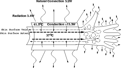
Due to the wearable computer's close proximity to the body, software and hardware become highly intertwined. For example, continuously monitoring a sensor results in an increased computational load. In turn, this either decreases the average battery life of the unit or increases the mass of batteries the user must carry. Both can dramatically effect the usage of the machine. In addition, the increased computation results in excess heat production which must be controlled for the machine to operate. Thus, such contextual interfaces as advocated above will force new designs in the construction of comfortable wearable computers.
To address this issue, analyses of user-derived power sources, heat dissipation, and weight or load bearing are presented. In addition, observations and lessons are offered from managing the hardware, software, and research support of a wearable computer community at the M.I.T. Media Laboratory for over six years.
The chapters in this dissertation detail a series of projects and experiments designed to progress toward more contextually-based interfaces. In most cases, the major contributions are the perceptual tools and models. Details on how to evaluate these systems are included. In addition, the chapters on power, heat, and load bearing address issues that will become critical as these more computationally intensive systems are adopted.
Developing a research infrastructure takes a considerable amount of effort and time. However, the process of designing the infrastructure provides crucial insights on how the technology might or might not be used. ``Everyday living'' with the infrastructure provides practical experience that can be gained no other way. The MIT Wearable Computing Project was no exception. As with any project exploring new hardware and metaphors of use, it transpired that some equipment was not practical once it was purchased and used, while other equipment became critical for effective use or experimentation. The members of the project often developed their own hardware drivers because commercial versions were unavailable or proved brittle in a mobile environment. This chapter will describe briefly the hardware and software that became central to the author's research and everyday use. The listed hardware and software was developed by the author or an undergraduate researcher under his immediate supervision except where noted otherwise. On a higher level, certain perceptual tools and modeling techniques became critical to the author's research and were packaged into advanced tool sets for use by the internal Media Laboratory community. Since these tool sets were used in different applications, they are described and developed in this chapter out of the context of a particular project. Later chapters will describe their use for particular applications and contrast the use of these tools to previous work in that particular domain.
Researching new methods of computing can lead to very divergent and incompatible hardware. To prevent this, I created and maintained a store of reference platforms, ranging from true everyday-use wearable computers to systems that simulated powerful future hardware or stored information for later analysis. These platforms enabled rapid prototyping of ideas and concentrated the results into a pool of knowledge and apparatus that could be built upon constantly and consistently. In addition, as the everyday-use wearables became more powerful, the applications that were prototyped on the simulation systems could be migrated to more casual use.
In late 1995, the Things That Think consortium at the MIT Media Laboratory decided to direct money into wearable computing research. Having already ordered PC/104 boards to upgrade my own wearable, I began to design inexpensive wearable computer ``kits'' that were highly customizable. By early 1996, the first monies were spent for this ``Wearables Closet,'' a library of hardware maintained for experimentation and rapid prototyping with wearable and embedded computing.
There were many considerations in the base wearable design. The low end system had to be inexpensive for embedded use but expandable to desktop performance. The system was intended to support everyday use [205], high end digital photography [130], augmented reality [214], and medical quality signal capture [160,162]. From earlier experimentation, I knew that form factor plays a crucial role in the use of such machines. The large flat surfaces of laptops, for example, are not very ergonomic for extended wear. Whatever the resulting form factor, the system had to fit in a piece of comfortable clothing for carrying. Another surprisingly crucial factor is battery life. For everyday use, the wearable should run a minimum of six hours on a charge. This way the user can create a daily routine of changing batteries during lunch time. Needless to say, no one commercial design satisfied all of these constraints, neither at the time nor currently.
To avoid supporting separate wearable computers for each user's needs, I chose to support the PC/104 board architecture and have each user manufacture his own wearable computer. The PC/104 standard is built around the concept of a stackable set of boards which connect via headers that are electrically identical to the standard 16-bit PC ISA bus of the time (the standard has since been extended to include PCI). The 3.6'' by 3.8'' boards stack vertically or can tile horizontally with special adaptors. PC/104 boards are developed by many vendors, support a surprising array peripherals, are rugged and heat tolerant, and often have enforced bounds on their power consumption due to their physical size.
I began to create a procedure for manufacturing wearable computers. The procedure needed to be simple enough that anyone who might need a wearable or embedded computer could follow it and produce a working machine in an afternoon. In addition, the procedure needed to reveal the functions of the underlying components and needed to teach the skills necessary in modifying the design so that the user would be confident in extending the system himself. One of the responsibilities of owning a wearable computer was tutoring of the other users on how to make their wearables. These philosophies proved useful in promoting the platform and extending its functionality. By the end of the first year the instructions were fairly robust, and approximately ten machines had been produced. As a personal goal, I wanted the procedure to be repeatable by researchers outside of the Media Laboratory as well, and the design adopted the name ``Lizzy'' from a talk by David Ross calling for a standardized open hardware design at the 1996 Boeing Wearable Computer Symposium. Unfortunately, making the design public proved difficult due to a shortage of parts during 1996. However, by January 1997 I had arranged for all of the components to be available through the suppliers, and I released the instructions to the MIT Wearable Computing Project's web site. A copy of these instructions can be found in Appendix B.
 |
 |
 |
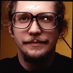 |
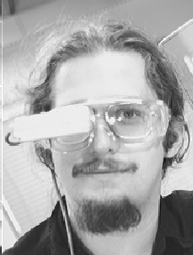
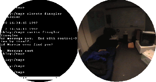
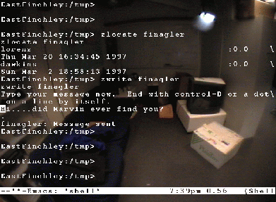
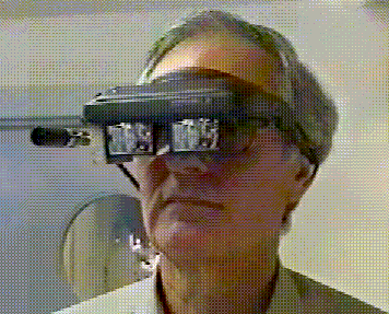
One of the most striking characteristics of a typical Lizzy wearable computer is its head-up display, Reflection Technology's Private Eye. This display produces 720 by 280 pixel resolution in monochrome red-on-black. It is fully addressable and its focus can be adjusted from ten inches to infinity. Typically, the Private Eye is mounted on the brim of a cap as in Figure 2-1 or in a pair of safety glasses as in Figure 2-2. The safety glasses mount holds the display directly in the line of sight for one of the user's eyes creating an overlay effect (see Figures 2-3 and 2-4). Such an effect is very useful for creating augmented realities. Over time, other displays were adapted for use as well, including modified cathode ray tubes [128], MicroOptical's display glasses (see Figure 2-5), and even the PalmPilot [89].
Another striking characteristic of the Lizzy is its keyboard, Handykey's Twiddler (see Figure 2-6). This 18 key chording keyboard is used with either hand and allows typing at up to 60 words per minute. The Twiddler also contains a mouse, activated by pressing a key with the thumb and rolling or pitching the unit for x or y movement respectively. This keyboard often provides the primary source of user input for a Lizzy.
In early 1996, a standard system consisted of a Private Eye, Twiddler, PC/104 based 50MHz 486 computer, 16M of RAM, and 815M of hard disk. Such a system required three PC/104 boards, and the standard 5.5'' by 5.5'' by 2.75'' enclosure could hold a maximum of four boards. By the time the instructions were released publicly, the system required only two boards, the processor speed had increased to 100MHz, and disk densities had increased. Internally to the project, stock was maintained for options such as 16-bit sound boards, video digitizers with on-board digital signal processors, PCMCIA adaptors, or extra communications ports as desired. Cameras, biosensors, alternative displays, extra disk capacity, higher end CPU boards, and custom clothing were also available. Another important option was wireless Internet connectivity through cellular digital packet data (CDPD) modems. Using Bell Atlantic Mobile's CDPD service, the wearable computers were assigned their own Internet address and appeared as a normal static workstation to the rest of the Internet. Service coverage grew to include many urban centers in the United States.
Linux is the operating system of choice for Lizzy design. Most other operating systems were too brittle for serious consideration or did not support the Lizzy's peripherals and were not open enough for the development of appropriate drivers. Consequently, much of the software produced by the Wearable Computing Project concentrated on producing open source for Linux. Among the software developed were drivers for HandyKey's Twiddler by Jeffrey Levine; the X11R6 windowing system on Reflection Technology's Private Eye display by Ben Walter; Sierra Wireless's PocquetPlus 110 CDPD wireless modem by Bayard Wentzel; Adjeco's ANDI-FG video digitizer by Ben Walter; General Reality's CyberTrack pitch, roll, and yaw sensor by Len Giambrone, and a general Global Positioning System decoder by graduate student Daniel Dreilinger. In addition, the Lizzy architecture created a focus for research on wearable-based software and hardware [174,209,89,76].
The Lizzy and related infrastructure have proved very successful, both internally and externally. Approximately twenty five Lizzys have been made internally from the Wearables Closet, and many more machines have been manufactured by researchers and hobbyists world-wide using the Lizzy reference design as a starting point. A benchmark for this success is that the supplier for the Private Eyes and their driver boards had run out of their stock of 100 by one month after the public release of the Lizzy instructions. At MIT, several Lizzy owners are everyday users in that, during a typical day, one can expect to see the user wearing his machine. However, perhaps the best indicator of success of the design, at least for everyday use, is the author's own system. While for many years the author would spend more time using his wearable than desktop machines, as of December 11, 1996 the author switched permanently from desktops to his wearable as his general computing device. In other words, almost all of the author's routine e-mail, web browsing, programming, and text editing, including the preparation of this document, is performed on a Lizzy-based wearable computer. Specifically, the author's system consists of a Private Eye, Twiddler, 133MHz 586 processor board with 20M of RAM, and a CDPD wireless modem. Run-time, without modem usage, is approximately 15 hours on two Sony NPF-950 lithium camcorder batteries, allowing for continuous use during the day.
Outdoors, the Global Positioning System (GPS) can be used to determine user location. However, for indoor use, a system of low-cost, infrared (IR), light-powered beacons called ``Locust'' was developed to serve this purpose (Figure2-7) [209,210]. Each Locust consists of a 4MHz PIC 16C84 microcontroller, a RS232 line voltage converter, infrared receiver, infrared LED, 6'' by 6'' 9V solar cell, and a voltage regulator. The Locust motherboard is derived from the IRX 2.0 by graduate student Rob Poor, and the resulting board is approximately 1" by 3". The IR LED on each locust is effective to about 20 feet, subtending an angle of approximately 38 degrees about the line of sight. Each Locust is programmed with a unique string of 4 symbols corresponding to its location. The Locust transmits these symbols repeatedly so that a listener, upon receiving the signal, knows his approximate location. A similar system has been described by Long et al. using television remote controls [126]. Since the Locust have to be numerous to cover an entire building, they are designed to be dependent solely on their solar cells so that battery replacement is not be an issue. These systems are typically mounted under fluorescent light fixtures where they can draw power and effectively cover a region.
In addition to being location beacons, the Locusts allow location-based information uploading. A short message, in this case one byte, is transmitted to a Locust. After the Locust receives the message, it retransmits the message, interleaved with its location information during the Locust's transmit cycle. This uploaded information may be self contained, or it may be a pointer to encrypted information stored elsewhere.
While one of the driving principles of the Wearable Computing Project was to design software and hardware for everyday use, much of the advanced research, such as found in this thesis, required more computing power than was available on wearable computers of the time. In order to simulate the more powerful wearable computers of the future, a full duplex wireless video system was designed. This proved valuable for integrating computer vision techniques into wearable computing applications. The first such system in the project, designed and implemented by graduate student Steve Mann [214,127], used amateur television bands. However, with the advent of cheap, unlicensed, and multi-channel 2.4GHz video and audio transmitters, the necessary equipment became much more accessible and could be placed in a shoulder bag. When combined with a small, head-mounted camera, a head-up display such as Virtual I/O's i-glasses or Sony's Glasstron, and a remote Silicon Graphics, Inc. (SGI) workstation, such a system can create the illusion of a powerful computer-vision driven wearable computer (see Figure 2-8). First the camera image of what the user is seeing is sent to the SGI. For most cases, an Elmo MN401E camera was used with a 15mm lens, selected to approximate the correct size of objects when viewed from the head-up display. The SGI analyzes the video and composites an appropriate ``wearable computer'' display for the situation on top of the incoming video. This image is then sent back to the head-up display where it is displayed. The entire process happens in real-time, only limited by the processing speed of the SGI and normal NTSC frame rate. The process is summarized in Figure 2-9, adapted from Starner et al. [214]. Note that an advantage to this system is that the user only sees the computer graphics when they are composited with the video image, insuring proper registration (ignoring latency effects between the video and graphics image). Thus, the issue of improper alignment of the head mounted display with the head mounted camera can be ignored.
 |
When designing a recognition system, a repeatable, stable database of input is needed for training and testing the system [96,211]. For several experiments described in this thesis, ``wearables'' had to be developed that could record information for such later reference. Figure 2-10 demonstrates a baseball cap with a downward-facing video camera embedded in its brim. The goal of this camera is to observe the wearer's hand, feet, and body motions. The resulting apparatus was used for recognizing sign language. The camera shown is an Elmo MN401E with a 4mm lens, which allows the largest field of view possible with this model. The camera head is about the size of a lipstick can and is tethered to a 4'' by 6'' by 2'' camera control box which outputs a high quality NTSC composite or svideo control signal. This camera cap was used in conjunction with a rack-mount Sony Betacam 2800 video recorder to produce high quality video tape of sign language, as will be discussed in the next chapter. Surprisingly, the video showed very little image vibration due to camera motion.
A completely mobile unit, capable of recording several synchronized channels of video, was desired for one of the experiments. For this system, a consumer grade Sony Hi-8 camcorder was used to record video. Since video of the scene in front of the user as well as video of his body motions was desired, a custom backpack of video equipment was designed. First, an Elmo QN401E ``matchstick-sized'' camera with a 2.2 mm lens was added to the camera cap in Figure 2-10 to observe a wide field of view ahead of the user. The cap was later replaced with the more durable matte black hard hat shown in Figure 2-11, and the downward looking MN401E camera remounted appropriately. While initially awkward and prone to more vibration than the cap, the hard hat provided a firm mount for both cameras. Both cameras require camera control units, which were placed in the backpack. Since the Hi-8 camcorder could record only one stream of video, a Presearch VQ42C quad display was employed. This unit can take up to four streams of composite NTSC video as input and output a composite video stream with each video stream subsampled and placed into separate quadrants of the image. In this manner, the camcorder could record synchronized video from both cameras. Figure 2-12 shows a functional diagram of the system. The system required over 40 watts of power, resulting in seven kilograms of batteries to run for two hours. Thus, a backpack was necessary to carry the apparatus comfortably. In addition, this video backpack provided protection for the equipment for the relatively harsh DUCK! environment described in later chapters.
Several tools were developed relating to the analysis and modeling of the user's actions and environment through video. While this section introduces these techniques, later chapters will apply them to particular problems, address previous work, and evaluate the resulting systems. Most of the tools in this section were used in conjunction with the wireless video system described above or used with data sets that were recorded for later reference and experimentation.
To increase the speed of prototyping vision-based systems, I produced a vision toolkit consisting of small, modular programs that can be reconfigured quickly through Unix pipes. Figure 2-13 shows this vision architecture and the projects involved. Some initial modules evolved from previous work with the ALIVE project [249] which tracks the entire user's body in a room-sized augmented reality.
Most clients of the vision architecture concatenate low level feature detectors, filters, and higher level, domain-specific feature detectors to determine necessary information. For example, ``BlobFinder,'' a low level module, tracks all the blobs of a certain range of colors in view of the camera and returns the shape parameters of those blobs. Parameterized filters remove trivially uninteresting blobs, and application-specific modules extract the parameters of the objects of interest. Finally, these parameters are passed to modeling or graphics applications as desired.
Each module can take input from Unix standard in, produce output on standard out, and describe errors through standard error. All interactions between modules consist of user readable ASCII text. A benefit of this design is that the user can easily observe the output at any given level of the vision system. Another benefit is that the output at any or all levels of the vision system can be logged by using the Unix ``tee'' command, enabling easy troubleshooting and experimentation. The flexibility and ease of use of this architecture allowed its use in several projects at the Media Laboratory and at affiliated sites [237,130,214,219]. The next sections describe each module in detail.
BlobFinder represents the lowest perceptual layer involved in the
vision architecture. Color NTSC composite video is captured and
analyzed at 320 by 243 pixel resolution. This lower resolution avoids
video interlace effects. To segment each blob initially, the
algorithm scans the image until it finds a pixel of the appropriate
color, determined by an a priori model or specified through use
of interactive sliders. A typical rule for testing whether a given pixel
should be included in the segmentation ![$p_T[x,y]$](img23.png) is
is
![\begin{displaymath}
p_T[x,y] = \left\{
\begin{array}{ll}
1 & \mbox{if $r[x,y]...
...\times slider3$} \\
0 & \mbox{otherwise}
\end{array} \right.\end{displaymath}](img24.png)
![$r[x,y]$](img25.png) ,
, ![$g[x,y]$](img26.png) , and
, and ![$b[x,y]$](img27.png) are the respective red, green,
and blue values for the pixel
are the respective red, green,
and blue values for the pixel ![$p[x,y]$](img28.png) and
and  ,
,  , and
, and
 are the current values of the sliders set by the user. The
sliders are given initial defaults, but changes in lighting, camera
quality, and digitizer quality often cause significant variations,
requiring the user to adjust the system to a color sample before
proceeding.
are the current values of the sliders set by the user. The
sliders are given initial defaults, but changes in lighting, camera
quality, and digitizer quality often cause significant variations,
requiring the user to adjust the system to a color sample before
proceeding.
Once a pixel of the right color is found, the region is grown from that pixel by checking the eight nearest neighbors. Any neighbor that is found to be the appropriate color is added to a ``grow list,'' and the initial pixel is removed from the grow list. Next, the color of the neighbors of each pixel on the grow list is checked. This process continues until there are no more pixels on the grow list [101]. Each pixel checked is considered part of the blob. This, in effect, performs a simple morphological dilation upon the resultant image that helps to prevent edge and lighting aberrations [101]. The centroid is calculated as a by-product of the growing step and is stored as a potential seed pixel for the next frame.
After extracting the blobs from the scene, second moment analysis is
performed on each blob. In effect, parameters are produced which
model each blob as an ellipse. The result is a nine element feature
vector for each blob consisting of the  and
and  position of its
centroid (as a rule, image positions are normalized from 0 to 1 by
dividing by the maximum horizontal or vertical image dimension as
appropriate), area in pixels, and major and minor axes as described by
normalized and offsets from the centroid and the axes' length.
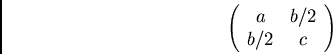
These last six parameters can be obtained by finding the eigenvalues
and eigenvectors of the matrix
position of its
centroid (as a rule, image positions are normalized from 0 to 1 by
dividing by the maximum horizontal or vertical image dimension as
appropriate), area in pixels, and major and minor axes as described by
normalized and offsets from the centroid and the axes' length.
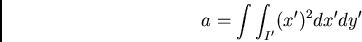
These last six parameters can be obtained by finding the eigenvalues
and eigenvectors of the matrix
 ,
,  , and
, and  are defined as
 and
and  are the and coordinates normalized to the
centroid)
are the and coordinates normalized to the
centroid)
Solving for the eigenvalues
The eigenvector corresponding to the larger of the two eigenvalues
indicates the direction of the the major axis, which is also the axis
of least inertia for the blob [93]. The length of the major
axis is twice the square root of the first eigenvalue. Similarly, the
minor axis is perpendicular to the major axis and has a length of
twice the square root of the second eigenvalue. It follows that the
eccentricity of the bounding ellipse can be found by determining the
ratio of the square roots of the eigenvalues. Note that there is a
180 degree ambiguity when describing the angle of the blob. Angles
are constrained to be between  degrees to address this
problem.
degrees to address this
problem.
BlobFinder can be reconfigured to report blobs of several specified colors through successive iterations through the video image. For example, all red and green blobs within a certain tolerance can be reported. However, BlobFinder is programmed to return a maximum of fifty blobs per color per frame. A required frame rate can be dictated to BlobFinder through command line arguments. If BlobFinder can go faster than the desired frame rate, it will slow down to match the given rate (using the Unix command ``select'' which frees the processor for other tasks). When BlobFinder can not meet its specified frame rate, it reports discrepancies to standard error output. In general, BlobFinder can maintain a 10-15 frames per second rate for most scenes using a 175MHz R5000 SGI.
SizeFilter's name implies its function. Reading a stream of blobs from standard input, SizeFilter outputs only those blobs consisting of more than a specified minimum of pixels. Blobs are output from largest to smallest in size. This filter is extremely useful in eliminating the many small blobs that can result from noise or small background objects in the video.
HandTrack tracks the user's hands using higher level information to eliminate extraneous blobs from the candidate blob list, identifies situations where the hands occlude each other, and correctly labels such situations. More specifically, this module tracks the hands over time and uses their expected size and position from one frame to the next to avoid confusion with other blobs. Handtrack assumes that the tracking camera is mounted above a desktop looking down at the user or that the tracking camera is worn in a cap and aimed down toward the wearer's hands, as described in the previous section. When a hand occludes the face, as in the case of the desktop version, or the nose, as in the case of the wearable camera, color tracking alone can not resolve the ambiguity. However, since the face or nose remains in the same area of the frame, its position can be determined and those pixels in the frame ignored. However, the hands move rapidly and occlude each other often. When occlusion occurs, the hands appear as a single blob of larger than normal area with significantly different moments than either of the two hands in the previous frame. In such situations, each of the two hands is assigned the features of this single blob. While not as informative as tracking each hand separately, this method retains a surprising amount of discriminating information. The occlusion event itself is implicitly modeled, and the combined position and moment information are retained.
FingerTrack is a simple version of HandTrack which attempts to
track the tip of an extended finger. In visually noisy environments the user
wears a specially-colored thimble. In this case, FingerTrack assumes
the largest blob is the tip of the finger. When the hand's natural
coloration is used, the system assumes the largest blob is the hand
and that topmost pixel in the blob is the tip of
the finger. Fingertrack outputs the fingertip's and position
in coordinates normalized from 0 to 1.
Fiducials are used in computer vision when accuracy and precision are desired in determining the position and orientation of objects [35,31,10]. Generally, these ``tags'' are designed to be distinct against their surrounding environment. In some cases, fiducials are designed to reflect infrared light or are themselves luminous [102]. In additional, a coding scheme can be used to uniquely identify each fiducial [172,173,146,35]. When an object is uniquely identified by a wearable computer, virtual information and behaviors can be assigned to that object, as will be described in later sections.
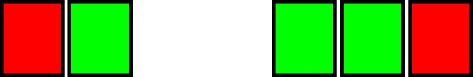
TagRec attempts to identify fiducials in the environment from blobs segmented by color, as produced by BlobFinder. Here, fiducials consist of a linear array of characters generated on low-cost miniature eight character LED signs or a linear arrangement of regularly-spaced red and green squares printed on small slips of paper. With the LED signs, the first and last characters always display an ``*'', and the middle characters show either an ``*'' or a blank. The middle characters indicate a unique ID through a simple binary code. For the printed tags, a red square marks the beginning and end of the tag, and the green squares act as the bits to indicate the ID of the tag (see Figure 2-14).
 |
The primary problem TagRec addresses is locating and identifying tags in the presence of noise. Noise, in this case, consists of other objects in the scene and spurious distortions from the camera's electronics that share the same colors as the tags. As an initial step, BlobFinder and SizeFilter find candidate blobs in the scene. For the LED tags, the thresholds for BlobFinder can be set so that there are very few candidate blobs that are not part of a valid tag. In order to determine if a group of blobs are part of the tag, TagRec examines the candidate list for blobs of approximately the same size. If these blobs meet a maximum size variance threshold, they are examined for linearity. Note that this test implies that an LED tag will consist of a minimum of three blobs. Finally, if the linearity test is passed, TagRec checks the spacing of the blobs to determine if they coincide with what is expected from the known geometry of the tag. A by-product of this step is the reconstruction of the identity of the tag.
Since the printed tags are not self-luminous, they can be harder to distinguish from the background. Thus, two distinct colors are used for each tag. From the blob candidate list, tuples of red blobs of similar sizes and the appropriate eccentricity are formed. Next, the line between the two red blobs is scanned for green blobs of the right relative size, linearity, and spacing as previously described. A valid tag must consist of two red squares and one or more green squares. If the resulting set of blobs is judged to be a tag, the blobs are removed from the candidate list and the process is repeated until no more valid pairs of red blobs remain. Note that this process is designed to avoid false positives.
Once an appropriate pattern is found, the identity of the tag is reconstructed by adding the values of the bits indicated by the internal squares. The presence of a square indicates an ``on'' bit. The internal squares are read left to right, with the leftmost square indicating the most significant bit. Since only seven of the characters are used on the LED tags, both the LED and paper tags contain five bits of potential information. Note the assumption is that the tag is read in the correct orientation. In other words, a tag that is upside down to the camera will have a different identity than when it is right side up. A simple way to eliminate this confusion is to equate tags and their reversed equivalents, halving the potential unique identities.
Besides identity, TagRec also returns the rotation and perceived distance of each tag. In fact, in situations where TagRec locates a tag but can not successfully identify it due to lighting or extreme rotation, TagRec will still report the tag's location and attributes. Rotation is calculated from the relative positions of the endpoints of the tag. Assuming the camera view is orthogonal to the surface of the tag and that the actual size of the tag and focal length of the camera are known, the perceived distance to the tag can be calculated from the distance between the tag's endpoints. Generally, only relative size was used in the applications to calculate a ``zoom factor,'' so true distance was not calculated. Theoretically, the perceived shape of the tag's squares could be used to determine the full 3D orientation of the tag relative to the camera. However, in practice, the tags would have to be fairly large or very close to the camera for effective shape recovery. Since part of the goal of the tag tracker is to be unobtrusive, large tags are unacceptable.
This module translates a stream of feature vectors to a format that Entropic's Hidden Markov Model Toolkit (HTK) can parse. Elements of the feature vector are assumed to be floating point numbers. Mainly designed for convenience, this module is adapted to whatever domain is needed. The only processing that may occur in this module is that the deltas of some features may be calculated and included in the output HTK feature vectors.
XFakeEvents provides a streaming interface for controlling the pointer in X Windows. XFakeEvents takes as input a stream of positions and mouse button combinations and generates appropriate events for the specified X Windows server. Originally written by then undergraduate Ken Russell, this module is extremely useful in interfacing perceptual systems to traditional desktop applications.
ColorSample is another simple, low level utility. Given a video image, ColorSample outputs the average color and luminance values for pre-defined regions in that image. There is no particular limit to the number of regions in the image; however, the number and size of the regions limit the frame rate of the utility. A desired frame rate can be specified as a command line option, and ColorSample will print error messages when it can not meet a given frame rate. If ColorSample can run faster than the given rate, it will slow down as appropriate.
VisualFilter, named for a technique championed by Mann [127], re-maps a video image on to a polygonal mesh based on specifications from a file. In effect, VisualFilter maps real-time video images on to polygons as if they were textures. The geometry of the polygons is stored in a modified point dictionary form [67] that includes which section of the video image should be mapped to which polygon. This system allows for visual re-mappings that are impossible with traditional lenses. While I originally wrote this utility for the SGI Onyx with Reality Engine 2 and Sirius video capture board, the same technique can now be used on much lower priced machines.
This module, adapted by Bernt Schiele from his doctoral thesis work [190,189,217], classifies video image patches based on multidimensional receptive field histograms. For training, a library of images, grouped into recognition classes, is selected. Each image is split into sub-images corresponding to the areas of most interest to create an image patch database. At run time, the system returns the probabilities for a given video image's patches matching patches represented in the library. Note that the number of probabilities returned per frame is the number of sub-images times the number of classes represented in the training database. In the specific system described later, a grid of 4 by 4 sub-images is used for three classes of actions resulting in 48 probabilities per frame. These probabilities can be used as features themselves. The system runs at ten frames per second on a SGI R10000 O2.
TimedData is a utility for playing back data. It reads a specified number of lines from its input and outputs these lines at the specified frame rate. In general, TimedData is used for testing or for demonstrations, which is why it doesn't appear in the architecture diagram.
Many of the vision toolkit modules described in the last section concentrate on generating and filtering feature vectors. This section will describe a method for recognizing events based on these feature vectors. Hidden Markov Models (HMM's), through Entropic's HTK toolkit, will be used in this thesis to recognize word signs in sign language, tasks in a ``paintball'' style game, and changes in location. Before the specifics of each of these systems can be discussed in subsequent chapters, a general overview on the training and testing of HMM's is necessary.
Hidden Markov models are used prominently and successfully in speech recognition and, more recently, in handwriting recognition [252,96,211]. Related to dynamic time warping, HMM's are extremely useful in modeling events characterized by features changing through time. Explicit segmentation is not necessary for either training or recognition, eliminating possible errors from pre-segmentation schemes. The output of the recognizer is a stream of time-stamped events that can be compared to a reference training stream for error calculation. In addition, models of language and context can be applied on several different levels. HMM's allow the tailoring of the model to the task selectively, knowledgeably, and scalably. Consequently, HMM's seem ideal for recognizing the complex, time-structured events that mark the everyday life of a user.
While a substantial body of literature exists on HMM technology [14,96,169,252], this section briefly outlines a traditional discussion of the algorithms. After outlining the fundamental theory in training and testing a discrete HMM, this result is then generalized to the continuous density case used in the experiments. For broader discussion of the topic, [96,169,206] are recommended.
A time domain process demonstrates a Markov property if the
conditional probability density of the current event, given all
present and past events, depends only on the  th most recent events.
If the current event depends solely on the most recent past event,
then the process is a first order Markov process.
th most recent events.
If the current event depends solely on the most recent past event,
then the process is a first order Markov process.
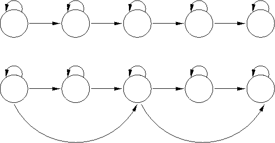
The initial topology for an HMM can be determined by estimating how many different states (i.e. events) are involved for each ``unit class.'' Examples of ``units'' include phonemes in speech [96], signs in sign language [219], or letters in handwriting [211]. A unit class is a particular type of unit. For example, the lowercase letters of the alphabet would be 26 classes in handwriting. Once an initial topology is chosen, fine tuning can be performed empirically for each class, by rerunning the same training and testing experiments with different topologies. To simplify the situation, one topology may be chosen for all classes. For example, for several applications in this thesis, an initial topology of five states was considered sufficient for the most complex class. To handle less complicated classes, skip transitions can be specified. Figure 2-15 shows a 5-state HMM with and without such skip transitions. In this case, the skip transitions allow the HMM to emulate a 3- or 4-state HMM. While a different HMM topology could be specified for each unit class depending on its complexity, similar accuracy gains can be realized by specifying one HMM model with appropriate skip transitions for all classes. Ideally, training for each unit class weights that class's model's transitions to emulate the appropriate HMM topology automatically. In research systems, such skip transition models are appropriate, since a great deal of time may be spent in optimizing a particular class's model at the expense of exploring better features or higher level relationships between models.
 |
In order to proceed more smoothly, a list of symbols that will be used in this discussion is provided below. The meaning for some of these variables will become clearer in context, but the reader is urged to gain some familiarity with them before continuing.
 : the number of observations.
 : number of states in the HMM.
 : distinct number of possible observations.
 : a state. For convenience (and with regard to convention in
the HMM literature), state
: a state. For convenience (and with regard to convention in
the HMM literature), state  at time
  will be denoted as
  .
.
 ; the set of states.
  and
and  will be used to denote
the set of initial and final states respectively.
will be used to denote
the set of initial and final states respectively.
 : an observation at time .
 : an observation sequence
 .
.
 : a particular type of observation.
: state transition probability.  represents
the transition probability from state to state .
represents
the transition probability from state to state .
 : the set of state transition probabilities.
: state output probability.  represents the probability
of generating some discrete symbol
represents the probability
of generating some discrete symbol  in state .
 : the set of state output probabilities.
 : initial state distribution.
 : a convenience variable representing a particular
hidden Markov model. consists of , , and .
: a convenience variable representing a particular
hidden Markov model. consists of , , and .
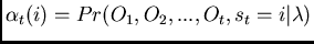
 : the ``forward variable,'' a convenience
variable.
: the ``forward variable,'' a convenience
variable.  is the probability of the partial observation
sequence to time and state , which is reached at time , given
the model . In notation,
is the probability of the partial observation
sequence to time and state , which is reached at time , given
the model . In notation,
 .
.
 : the ``backward variable,'' a convenience variable.
Similar to the forward variable,
: the ``backward variable,'' a convenience variable.
Similar to the forward variable,
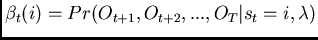 , or the probability of the partial
observation sequence from
, or the probability of the partial
observation sequence from  to the final observation , given
state at time and the model .
to the final observation , given
state at time and the model .
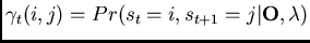
 : generally used for a posterior
probabilities.
: generally used for a posterior
probabilities.  will be defined as the probability of
a path being in state at time and making a transition to state
at time , given the observation sequence and the particular
model. In other words,
will be defined as the probability of
a path being in state at time and making a transition to state
at time , given the observation sequence and the particular
model. In other words,
 .
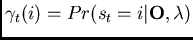
.  will be defined as the posterior
probability of being in state at time given the observation
sequence and the model, or
will be defined as the posterior
probability of being in state at time given the observation
sequence and the model, or
 .
.
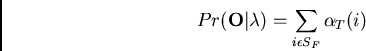
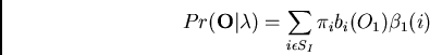
There are three key problems in HMM use. These are the evaluation
problem, the estimation problem, and the decoding problem. The
evaluation problem is that given an observation sequence and a model, what
is the probability that the observed sequence was generated by the
model (
 )? If this can be evaluated for all
competing models for an observation sequence, then the model with the
highest probability can be chosen for recognition.
)? If this can be evaluated for all
competing models for an observation sequence, then the model with the
highest probability can be chosen for recognition.
can be calculated several ways. The
naive way is to sum the probability over all the possible state
sequences in a model for the observation sequence:
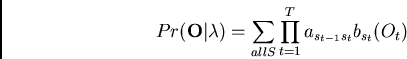
The initial distribution  is absorbed into the notation for
 for simplicity in this discussion. The above equation
can be better understood by ignoring the outside sum and product and
setting
for simplicity in this discussion. The above equation
can be better understood by ignoring the outside sum and product and
setting  . Assuming a particular state sequence through the model
and the observation sequence, the inner product is the probability of
transitioning to the state at time 1 (in this case, from the initial state) times
the probability of observation 1 being output from this state. By
multiplying over all times 1 through T, the probability that the state
sequence and the observation sequence occur together
is obtained. Summing this probability for all possible state
sequences produces
. However, this method
is exponential in time, so the more efficient forward-backward
algorithm is used in practice.
. Assuming a particular state sequence through the model
and the observation sequence, the inner product is the probability of
transitioning to the state at time 1 (in this case, from the initial state) times
the probability of observation 1 being output from this state. By
multiplying over all times 1 through T, the probability that the state
sequence and the observation sequence occur together
is obtained. Summing this probability for all possible state
sequences produces
. However, this method
is exponential in time, so the more efficient forward-backward
algorithm is used in practice.
The forward variable has already been defined above. Here its inductive calculation, called the forward algorithm, is shown (from [96]).
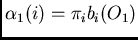 , for all states (if
 ;otherwise )
 along the time axis, for
  ,
and all states , compute
,
and all states , compute ![\begin{displaymath}\alpha_t(j) = [\sum_i\alpha_{t-1}(i)a_{ij}]b_j(O_t)\end{displaymath}](img90.png)
The first step initializes the forward variable with the initial
probability for all states, while the second step inductively steps
the forward variable through time. The final step gives the desired
result
, and it can be shown by
constructing a lattice of states and transitions through time that the
computation is only order  where is the number of states
and is the number of observations.
where is the number of states
and is the number of observations.
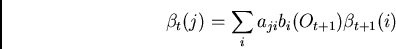
Another way of computing
is through use of
the backward variable , as already defined above, in a similar
manner.
 , for all states
 ;
otherwise
;
otherwise 
 along the time axis, for
 and all states , compute
The estimation problem concerns how to adjust to maximize
given an observation sequence .
Given an initial model, which can have flat probabilities, the
forward-backward algorithm allows us to evaluate this probability.
All that remains is to find a method to improve the initial model.
Unfortunately, an analytical solution is not known, but
an iterative technique can be employed.
Using the actual evidence from the training data, a new estimate for the respective output probability can be assigned
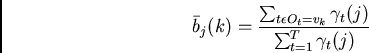
where is defined as the posterior probability of being
in state at time given the observation sequence and the
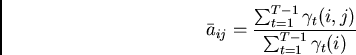
model. Similarly, the evidence can be used to develop
a new estimate of the probability of a state transition
( ) and initial state probabilities (
 ).
Thus,
).
Thus,
Initial state probabilities can also be re-estimated through the formula
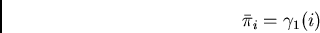
Thus all the components of , namely , , and can
be re-estimated. Since either the forward or backward algorithm can
be used to evaluate
 versus the
previous estimation, the above technique can be used iteratively to
converge the model to some limit. While the technique described only
handles a single observation sequence, it is easy to extend to a set
of observation sequences [96,14,252].
versus the
previous estimation, the above technique can be used iteratively to
converge the model to some limit. While the technique described only
handles a single observation sequence, it is easy to extend to a set
of observation sequences [96,14,252].
While the estimation and evaluation processes described above are sufficient for the development of an HMM system, the Viterbi algorithm provides a quick means of evaluating a set of HMM's in practice as well as providing a solution for the decoding problem [96]. In decoding, the goal is to recover the state sequence given an observation sequence. The Viterbi algorithm can be viewed as a special form of the forward-backward algorithm where only the maximum path at each time step is taken instead of all paths. This optimization reduces computational load and additionally allows the recovery of the most likely state sequence. The steps to the Viterbi algorithm are
,
 ;
;

 to and for all states ,
![$\delta_t(j)
= Max_i[\delta_{t-1}(i)a_{ij}]b_j(O_t)$](img109.png) ;
;
![$\psi_t(j)=argmax_i[\delta_{t-1}(i)a_{ij}]$](img110.png)
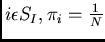
![$P = Max_{s \epsilon S_F}[\delta_T(s)]$](img111.png) ;
;
![$s_T=argmax_{s \epsilon S_F}[\delta_T(s)]$](img112.png)
 to
to  ,
,
In many HMM system implementations, the Viterbi algorithm is used for
evaluation at recognition time. Note that since Viterbi only
guarantees the maximum of
 over all (as a
result of the first order Markov assumption) instead of the sum
over all possible state sequences, the resultant scores are only an
approximation. For example, if there are two mostly disjoint state
sequences through one model with medium probability and one state
sequence through a second model with high probability, the Viterbi
algorithm would favor the second HMM over the first. However,
Rabiner [169] shows that the probabilities obtained from both
methods are typically very close.
over all (as a
result of the first order Markov assumption) instead of the sum
over all possible state sequences, the resultant scores are only an
approximation. For example, if there are two mostly disjoint state
sequences through one model with medium probability and one state
sequence through a second model with high probability, the Viterbi
algorithm would favor the second HMM over the first. However,
Rabiner [169] shows that the probabilities obtained from both
methods are typically very close.
In practice, the Viterbi algorithm may be modified with a limit on the lowest numerical value of the probability of the state sequence, which in effect causes a beam search of the space. While this modification no longer guarantees an optimum result, a considerable speed increase may be obtained. Furthermore, to aid in estimation, the Baum-Welch algorithm may be manipulated so that parts of the model are held constant while other parts are trained.
So far the discussion has assumed some method of quantization of feature vectors into classes, but it is easy to see how the actual probability densities might be used. However, the above algorithms must be modified to accept continuous densities. The efforts of Baum, Petrie, Liporace, and Juang [15,14,124,107] showed how to generalize the Baum-Welch, Viterbi, and forward-backward algorithms to handle a variety of characteristic densities. In this context, however, the densities will be assumed to be Gaussian. Specifically,
Initial estimations of  and
and  may be found by dividing
the evidence evenly among the states of the model and calculating
the mean and variance in the normal way.
may be found by dividing
the evidence evenly among the states of the model and calculating
the mean and variance in the normal way.
Whereas flat densities were used for the initialization step before, here the evidence is used. Now all that is needed is a way to provide new estimates for the output probability. We wish to weight the influence of a particular observation for each state based on the likelihood of that observation occurring in that state. Adapting the solution from the discrete case yields
and
In practice,  is used to calculate
 instead of the
re-estimated
instead of the
re-estimated  for convenience. While this is not
strictly proper, the values are approximately equal in contiguous
iterations [96] and seem not to make an empirical difference
[252]. Since only one stream of data will be used and
only one mixture (Gaussian density) will be assumed, the algorithms
above can proceed normally incorporating these changes for the
continuous density case.
for convenience. While this is not
strictly proper, the values are approximately equal in contiguous
iterations [96] and seem not to make an empirical difference
[252]. Since only one stream of data will be used and
only one mixture (Gaussian density) will be assumed, the algorithms
above can proceed normally incorporating these changes for the
continuous density case.
When using HMM's to recognize strings of data such as continuous speech, cursive handwriting, or American Sign Language sentences, several methods can be used to bring context to bear in training and recognition. A simple context modeling method is embedded training. While initial training of the models might rely on manual segmentation or, as in this thesis, evenly dividing the evidence among the models for an automatic initial estimate, embedded training trains the models in situ and allows model boundaries to shift through a probabilistic entry into the initial states of each model [252].
Often, a unit can be affected by both the unit in front of it and the unit behind it. For phonemes in speech, this is called ``co-articulation.'' While this can confuse systems based on recognizing isolated units, the context information can be used to aid overall recognition. For example, if two units are often seen together, recognizing the two units as one group may be beneficial.
A final use of context is best described as the inter-word level in speech (speech processing can be thought of on three levels: phoneme, intra-word, and inter-word). This is one level removed from the inter-unit context described in the preceding paragraph. Statistical grammars relating the probability of the co-occurrence of two or more words can be used to weight the recognition process. Grammars that associate two words are called bigrams, whereas grammars that associate three words are called trigrams. Rule-based grammars can also be used to aid recognition.
This section described the foundations for hidden Markov models without regard to their application. Subsequent chapters which use this framework will address the details on how to evaluate and tune an HMM-based recognizer for their specific domains.
We are confronted with insurmountable opportunities. Walt Kelly, ``Pogo''
This chapter will attempt, through various anecdotes, to communicate the experience of everyday life augmented with a wearable computer. A departure from the rest of this thesis, this chapter will not describe a particular experiment, technique, or piece of apparatus but instead try to convey the sense of value of this lifestyle. These examples are provided in the spirit of Fred Brooks's sentiments that ``any data is better than none'' when pursuing a new direction of research [24].
The experiences of the everyday users in the MIT wearable computing community are unique in several respects. While wearable computing research generally concentrates on particular industrial or military tasks [102,200,197,66,149,155], much of the focus of the MIT project was improving the normal, civilian life of the participants. A similar mind-set can be found in the ubiquitous computing [243] work based at Xerox's research centers [191,114,16]. However, their research concentrated on small pen or touch devices not intended to replace the desktop. These devices were less apparent to bystanders than the early MIT wearables, causing significantly different social phenomena. Due to the nature of these devices, the user interface was not as readily available to the user, as will be evident in the first anecdote. In addition, MIT wearable computer users were facile in modifying their own software and hardware, having had to construct their own personal machines. This led to a continually evolving platform that manifested itself differently in both clothing fashion and functionality with each user.
``Excuse me, what time is it?'' asked a fellow pedestrian.
Making eye contact while continuing to walk, I glanced at the clock on my word processor and replied ``6:23.''
The pedestrian suddenly looked puzzled, since I had not looked at my wrist but had provided a specific answer. ``Uh, if you don't mind my asking, how do you know?'' he queried.
``My clock says so. This is my computer display.'' I replied, touching my eyeglasses.
This simple exchange summarizes one of the major issues with new technologies: no one has formed a mental model of its use. In some cases, this can cause social awkwardness for early users, as in the instance above. Such situations generally follow a certain ``script'' [188]. Someone asks the time. The queried individual rotates her wrist, raises her arm, looks at her clock, and after a pause, speaks the time. With a head-up display, it takes a fraction of a second to attend a clock displayed in a known position, and often the conversational partner will not even notice the eye movement. Thus, it can appear as if the user has invented a time just to be rid of the query. This was the thought of the pedestrian in the above anecdote given his tone of questioning. In such situations, the author began to question his partners in these spontaneous conversations to understand their preconceptions.
In 1994, I was exploring a zoo in Sydney when some Australian tourists approached me.
``Is that a camcorder?'' they asked.
``No, it's my computer, but I get that mistake all the time,'' I replied, ``Why did you think it was a camcorder?''
The tourists associated the display covering my left eye with the view finder of a camcorder. While they hadn't seen a lens, they just assumed that the actual camera was held somewhere else, in the hand for example, and that the view finder was mounted on the safety glasses for convenience. Thus, they had assigned a particular functionality to my equipment based on their experience with similar looking products.
Unfortunately, such preconceptions can be difficult to correct, and I've often spent an hour, even with a fellow academic in the field, trying to correct false expectations. However, once both the users of a technology and bystanders have a model of the technology's use, social patterns evolve to enfold the new equipment and capabilities. We are continually discovering new uses for wearable computers, and some of these uses are very subtle. In fact, unadorned colleagues often do not realize the extent to which the wearable computers are used for a wide range of applications. This section details the uses of the Lizzy wearables that are most similar to desktop machines or portable consumer electronics. Later sections will emphasize uses of the Lizzy that have been tailored toward a wearable apparatus. Please note that these sections are not designed to be complete, since such a task would easily fill a book and is not appropriate for this thesis.
``But what do you use it for?'' asked the mother of two small children as we stood in line to board the plane.
Wearable computer users are frequently the center of attention at airports. However, fellow travelers are often reluctant to ask about the equipment unless they happen to be in the immediate vicinity of the user. The question above is one of the most commonly asked, and I find it is also the hardest to answer in thirty seconds. I often respond with what I happen to be doing at the time. Usually it is something mundane, like reading e-mail or looking up connecting flight information. However, in this case I could respond honestly, ``Well, as we are boarding I am finishing a paragraph of my PhD thesis.''
Wearable computing makes traditional desktop applications nearly ubiquitous. With the Lizzy, all the ``user resources'' needed for traditional desktop applications are one hand and one eye. Thus, the interface is available during most of the user's daily life, which can be especially gratifying during pointless periods of waiting as in the situation above. However, this capability can be liberating in other ways as well. For several years my office has been used as a laboratory since I could work just as effectively anywhere I could sit in the public spaces. This ability led to a more social work ethic on my part in that I would make a point in performing my work in different groups' laboratories. In this manner I could take advantage of the Media Laboratory's diversity to learn informally how different disciplines operate.
However, the wisdom of using every application in every environment may be questioned. For example, it is not hard to see why one should not play video games while crossing a busy street! However, I often write e-mail while strolling through Cambridge. Since Lizzy users touch type, such a task does not require much visual attention. In such circumstances the screen may be mostly ignored except for identification of gross errors, such as typing into the wrong application.
A bit more limiting a task is reading e-mail. Yet, I find this task acceptable when navigating MIT's hallways. Setting the Private Eye's focus at infinity, the text seems to float on top of the throng of my fellow students, through whom I must navigate. The user can maintain an awareness of the physical environment around him while focusing his attention on a task in his virtual environment. If he comes to a street or is suddenly confronted with an out-of-control bicycle, he can quickly switch his concentration to the physical environment, ignoring the virtual. This is certainly favorable to alternative methods. For example, at MIT Norbert Weiner was famous for reading a book in his left hand while keeping the little finger of his right hand in contact with the wall so he would know when he reached an intersection. Current PDA users have an even worse situation for mobile reading, as one hand is needed to hold the PDA, the other hand manipulates the pen for scrolling, and both eyes are focused downward to the screen.
Similarly, the head-up nature of the Lizzy interface allows small breaks to be used productively. For example, my emacs text processor loads my ``to-do'' list when I start it. In general, this list is kept as my primary buffer so that once I complete a task, it reappears. In the thirty seconds required to walk from one office to another, I glance at this list, possibly reorganizing it to reflect my new priorities. Not only does this interactive approach help my memory, but it also helps with stress reduction. While the list grows to be quite large, the most important items remain on top and, due to its mutability, I feel as if I am controlling the list instead of the list controlling my behavior. Similarly, my calendar always remains in the background and is quickly accessible.
``What do you mean you read books on your wearable? How do you get them in there?'' asked a colleague from another school.
I responded, ``Most books are type-set electronically before they are printed, so sometimes the authors will just mail me their book as long as I agree not to release it myself. In other cases I use a band saw on the spine of the book and run the pages through an optical character recognition program with an automatic scanner. That's what I try to do with most of my professional books and some of my reading for enjoyment.''
``Seems like an awful lot of trouble to read a book.''
``Actually, due to tricks that speed up my reading on my wearable, I feel that the entire process takes about the same amount of my time as if I read the book directly.''
Such a statement, which I do not claim to support rigorously, may seem implausible at first. However, the reader should take into account some of the author's personal failings. First, I can not keep track of a physical bookmark and lose my place routinely. Due to my tendency to read several books concurrently, I generally misplace at least one, being unable to transport all the books all the time. In electronic form, a standard novel requires less than one megabyte without compression. Thus, I can transport as many books as I want once they are scanned. In addition, I can reformat a book to newspaper column size, which is more convenient for my reading style. Once loaded into emacs, I have the book immediately accessible all day, and pressing ``page down'' on the Twiddler is faster than turning a page physically. In addition, I have a special chord defined on my Twiddler as a ``bookmark'' that I place as I read. Searching for this unique bookmark requires two keystrokes, which is faster than finding my place in a physical book. If I find a particular passage interesting, I mark it as such using another chord, corresponding to ``%!.'' This keystroke is significantly faster than locating and using a highlighter pen. In addition, when looking for an important passage in the book later, electronic search is significantly faster than paging through the physical artifact and visually scanning each page. In point of fact, the Negroponte quote in the introduction was taken from a scanned version of his book which was annotated in such a manner. Another feature I use surprisingly often when reading is an electronic dictionary. When a couple of chords return a definition of an unknown word in a second, it is hard to justify being too lazy to look up that word. In addition, with such easy access to an electronic thesaurus and dictionary, spontaneous arguments in conversation over word usage resolve quickly.
On a more adventuresome trip, a fellow graduate student and I went to England to demonstrate one of the group's research projects. The demonstration required a supercomputer which was rented for the occasion and valued at approximately two hundred thousand dollars. In installing our computer vision system, we had to move this computer. Upon powering the system, the supercomputer would not boot, whereas it had previously. After several frantic attempts at fixing the problem, which did not amuse our hosts since they were personally financially responsible for the equipment, I connected my wearable to the supercomputer's boot monitor serial port to observe the process at a lower level. To our relief, the machine was soon fixed, though to this day I don't know exactly what I did.
As a computer scientist, one of the benefits of wearing a computer is having constant access to a known system with which you are intimately familiar. My wearable has acted as an impromptu diagnostic tool for file servers, cellular phone sites, and local area networks and as a large file transfer buffer for an emergency network at a conference. With the advent of field programmable gate array (FPGA) test instruments that can be reconfigured and interfaced via the parallel port, we are beginning to connect oscilloscopes, multi-meters, and multi-channel digital logic analyzers to the Lizzy to take advantage of the Lizzy's head-up display and large data capture capability. Using a Lizzy for testing is often much more convenient than a laptop since the user maintains mobility and can use his free hand to hold test probes. In many senses, the Lizzy is becoming an all-in-one mobile test facility. Similarly, the Lizzy has been adapted to be a portable entertainment center. Video games, short movies, and music have been known to reside on the MIT Lizzys [89].
One of the reasons I began prototyping wearable computers was due to my perception of a failure of standard classroom techniques. As a student, I could either attend to and understand the lecture or copy the blackboard verbatim, but not both. Unfortunately, if I concentrated on the former my understanding would disappear in as little as a couple of hours. If I concentrated on the latter, I couldn't reconstruct the concepts or, in some cases, understand my own handwriting upon review. Using a laptop computer helped but was not sufficient. I could type much faster than I could write, but the continual movement of my head and refocusing of my eyes between the screen and the blackboard took considerable effort. With my wearable, I could focus the display at the same distance as the blackboard. In addition to eliminating head motion and eye strain, the system allowed me to maintain a peripheral awareness of my typing while I concentrated on the subject of the lecture. With the Twiddler, I could hide my hand under my table or chair, making its key clicks virtually unnoticeable in a normal classroom. I had found a way to take good notes while still understanding the lecture.
An unexpected effect of using the wearable was that it sharpened my concentration during lectures significantly. Years later, I heard an independent wearable computer hobbyist describe how he uses his wearable to overcome a clinical case of attention deficit disorder and maintain a job as a system administrator. This raises an interesting, unanswered question: can wearable computers help provide attentional focus through information support? A study on the subject would be fascinating.
``When you wear your display, how can I tell if you are paying attention to me or reading your e-mail?'' a colleague asked in 1993, after I returned with the lab's first wearable.
``Simple: watch my eyes. If they scan back and forth, I'm reading e-mail. Otherwise, I'm looking at you,'' I answered.
``Then why do you wear your computer when talking with people?''
``I find that the most interesting conversations occur spontaneously, just when you are the most unlikely to have the ability to remember the parts that you want. With my wearable I find I can enter the most salient portions of the conversation without interrupting the flow of it. In fact, while at BBN I found that people soon grew so accustomed to the hardware when talking to me that they could not tell you after the fact whether or not I was wearing the display for the conversation.''
``I doubt that, but why not just use pen and paper?''
``Because writing with pen and paper is very obvious and attention grabbing for the person who is talking. The process of remembering the conversation interrupts the conversation itself. With the keyboard at my side and my maintaining eye contact you probably did not notice that I've been taking notes on this conversation.''
``Actually, no I didn't!''
In an interesting case of self reference, I have been collecting the anecdotes for this section in much the same manner over the past six years. Lizzy users have remarked that it is easy to take notes during a conversation, and I've found the interface socially graceful to do so. A common game played by unadorned colleagues, once they understand the machine's purpose, is to guess when the machine is being accessed in a conversation. Personally, I've found that unless the observer specifically watches the user's hands, he often confuses the eye motions that occur in natural discourse with glances at the display. This confusion is probably due to the observer's misconception that the wearable user must look at his screen to type.
Notes taken during a conversation are often terse, using just enough words for the note taker to reconstruct the concepts later. Where appropriate, a direct quote may be included. For such instances, I've found that I have about a natural five word ``typing buffer'' in that I can remember five words and type them with very little cognitive load while still attending to the conversation. Interestingly, I began to collect quotes a few months after beginning everyday use of my wearable computer.
``It's interesting,'' I commented to another Lizzy wearer during an impromptu research meeting, ``that when we talk about our research plans, we have natural breaks in the conversation that I think an observer unfamiliar with wearables would fail to understand. I guess that it is because we are attuned to when the other is writing down notes or searching for some background material. You know, another thing I find I do is keep an emacs scratch buffer open and enter a word or two about points I want to raise in the conversation later.''
``So do I,'' replied my colleague. ``It seems a good way to remember what you wanted to say and determine if we fully explore the conceptual space of a topic. Not to mention that if it was a good conversation, having notes on your own contributions makes adding detail later easier.''
``I must admit that I often do not take notes on what I say in a conversation except in situations like this one. Why should I take notes on what I know intimately already? Another tendency I've observed is that I rarely go back and edit or add to my notes of a conversation unless it has deep significance. In such cases, though, I tend to organize the conversation's file while walking to my next appointment, which helps reinforce the major points.''
This conversation was held with another long-term wearable computer user. I was quite surprised to find we had both evolved this method of conversation where we used something akin to a personal blackboard to track and form conversations. Later, while observing more junior users, I found that they formed similar habits. Examining my own behavior while ``brainstorming'' alone, a similar use of the wearable appeared. It is as if wearable users exploit the extra memory of their computer to ``place-hold'' general concepts as they think deeply about specific implications. Alerted to this concept, I began to examine my research conversations and discovered hierarchies in the notes I had taken. On the other hand, my earliest notes on the wearable were much more scattered. Of course, this could be the effect of growing maturity as a scientist, but the phenomenon merits further inquiry in the future. What is difficult to convey in these anecdotes is the deep sense of property associated with the files of notes taken over the years on a wearable. I often feel that many of my thoughts and feelings are stored in these notes, though the conceptual short hand that I use makes them difficult to interpret by all except closest collaborators.
``What did we say was the importance of deixis?'' asked the lecturer. With the end of the term approaching, the class was reviewing their study of discourse analysis.
Volunteering, I said, ``We said the importance of deixis is ... uh ... uh ... humph, whoops! Uh, I'll get back to you on that.''
The class, most of whom were Media Laboratory graduate students familiar with wearable computing, began to laugh. I had not known the precise wording of the answer and had tried to retrieve my class notes on the topic. Having done this routinely in the past, I had expected to have the information in time to complete my sentence. Due to a complex series of mistaken keystrokes, I had failed so badly that I could not cover my error, much to everyone's amusement.
One of the members of the class leaned over and said, ``You actually do that sort of thing all the time, don't you? Now I'm impressed.''
It was only because of a dramatic failure that my colleagues realized that I use my wearable for information retrieval on a day to day basis. Even today, people that I've worked with for years are surprised when some slip makes it evident that I use the interface in such a time critical manner.
With the ease of capturing information enabled by a wearable computer, users tend to type volumes of notes on all aspects of life. This large amount of text creates the corresponding problem of timely retrieval. How can the user keep track of everything? Personally, I use a system of directories that distinguish between classes of notes: conferences, meetings, classes, sponsor visits, wearable computing issues, ideas, and everyday, practical information. In addition, I maintain separate directories for papers, books, my own writings, and e-mail. Generally, I can locate the appropriate file on a given topic within a couple of key strokes, as mentioned above. However, this direct approach assumes that I know I have information on a given topic. With over 1300 files in just my wearable computing and practical notes directories, this assumption is not valid. Thus, an early question that formed from the use of a wearable computer was how could the computer aid in the discovery and use of my own ``memories?''
As noted in the introduction, most computer interfaces are designed for explicit control by the user. In many respects, this is an artifact of the current physical design of the desktop ``workstation.'' When the user wants to perform a task on a computer, he walks to his desk and turns on a machine. Computational assistance is associated with a particular location and device that requires a lengthy starting process before it becomes useful. In many senses, the ``affordances'' of computers constrain their perceived use [154,77]. What happens when these affordances are changed to suggest interactions where the manipulation of the computer interface is not the primary task of the user? For example, what if the computer performs secondary information assistance tasks augmenting the user's capabilities in reaching a primary goal?
The first interface that I prototyped in this vein is the Remembrance Agent (RA). The idea is simple. While the user types with his word processor, the Remembrance Agent continuously searches the user's disk for files or e-mail that contain similar terms to what the user is typing. The top three files that match in this manner are displayed with one line summaries describing their content in the bottom of the user's window. While the user types, the RA updates its ``hits'' every ten seconds. The user mostly ignores this unobtrusive, automatic service but occasionally glances down and sees a description that cues his own memories of something important to his work [214]. While the user might not have recalled the piece of information on his own, he recognizes the significance (or lack of significance) of the one-line summary and can request the RA to bring up the associated file or e-mail for further inspection. This sort of interface ``increases serendipity'' for the user. While the continuous presentation of information requires little user attention, much of the effectiveness of the interface depends on ``chance'' encounters of useful information. Thus, the Remembrance Agent creates a symbiosis between the highly associative memory of the user with the perfect recall and tireless nature of the computer.
While I created this concept for a class project in 1993 [205], Bradley Rhodes has developed the idea, implemented and supported the software to make it feasible for everyday use, and has shown that the concept generalizes to other domains and other modalities of data [176,214,174]. Figure 3-1 shows an early example session with the Remembrance Agent.
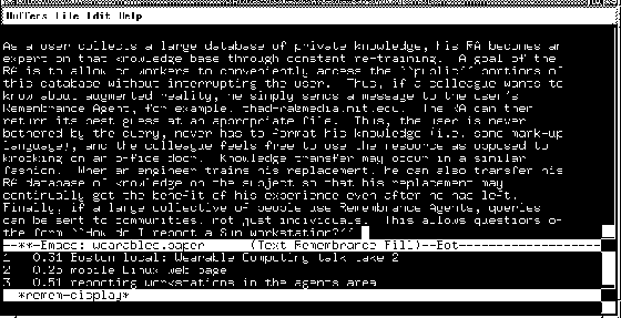 |
Preparing for the oral exams on the way to my doctorate, I downloaded or scanned almost every reading my committee assigned. A separate Remembrance Agent index was created for these readings, and I ran the RA during my entire exam. As noted earlier, when involved in a research discussion, I make notes to myself to organize my thoughts. The RA used these notes to suggest appropriate readings for each question. While the RA performed exceedingly well for this task, my knowledge of the domain was such that the RA performed the services of a ``security blanket'' more than anything else.
Toward the end of the exam, the faculty observer exclaimed, ``Hey Thad, are you doing what I think you are? Is the RA running in there?''
Surprised, since I thought this issue had been resolved in the various classes I had taken, I answered ``Yes, this particular application was part of the reason I worked on it.''
The discussion that followed paralleled that of earlier discussions about test-taking. Is such an ``augmented memory'' allowable? Is it fair? In many respects, the wearable computer is simply the equivalent of the textbook in an open book exam, except that it is pro-active and searchable. What about a closed book exam? Academically, isn't the point of a closed book exam to test how the student would apply his knowledge in the field where he could not transport his library or might not have the time to reference his books? However, with the wearable computer running the Remembrance Agent, the student could have a pro-active library with him continuously. From many years of collaboration, my committee knew that I am, in fact, rarely parted from my machine. Thus, the test was valid, since this exam could have occurred at just about any time and I would have had the same information support.
``Hold it, what about his Internet modem?'' asked an examiner.
``I can not get reception in this basement classroom,'' I responded. ``Unless told otherwise, I've considered such collaboration during exams to be cheating.''
Thus, after several minutes of discussion, the committee allowed me to finish and considered the confiscation of Internet modems from wearable computer users for future exams.
This anecdote brings up an interesting point. If I can store my textbooks and memories on the wearable's hard disk, why not download the Library of Congress? Unfortunately, such an application breaks the familiarity conditions necessary for the RA to be effective. The user must have enough personal knowledge of the RA's database to recognize the importance of a file or e-mail based on its one-line summary. Without this intimate knowledge, the RA's suggestions are relatively useless. In other words, the Remembrance Agent can't implant random memories into its users.
However, the notes of a close collaborator, who shares the same vocabulary and some of the same experiences, might prove useful to an RA user. As an informal experiment, three wearable computer users combined their notes. RA suggestions from a colleague's database can be quite disquieting. The user recognizes the significance of the suggestion and can almost claim the memory as his own due to the similarity with his own experiences, but he knows that it isn't his entry. These ``shadow memories'' create an asynchronous form of collaboration, one of the most dramatic instances of which is related below.
One of the duties of a Media Laboratory graduate student is demonstrating his projects to sponsors. Over time, wearable computer demonstrations became popular. Fortunately, with several wearable computer users in the laboratory, each with his own specialty, demonstrations can be distributed so as not to put an undo burden on any particular individual. For my demonstrations, I maintain a file that details my primary talking points. Not only does this improve my short presentations, but it also reinforces the use of the machine to the visitor when he tries wearing the display. To provide further aid, I keep a list of answers to common questions that are asked during demonstrations.
A few days before my colleagues and I merged our RA databases, I was asked a new question by a sponsor. Knowing that I speak better if I have a detailed response at hand, I used my notes from the conversation to write a few sentences addressing that question immediately after the demonstration.
At the end of that week I was working in a different group's laboratory, when I heard a colleague begin a wearables demonstration. Hidden from view, I kept working. However, at the end of the demo, I heard the same, new question asked by this different sponsor. Surprised, I finished writing the sentence I was working on and rose to introduce myself when I heard the presenter reply with the exact answer I had written just a few days before!Suddenly, the utility of sharing up-to-date ``notes'' became apparent, for I had not spoken, written, or otherwise articulated this new information to my colleague except through the massive merging of databases. However, he was still able to find and use the information appropriately at the time it was needed. While I do not know if this ability was due to an RA suggestion or my colleague's own quick action in finding the appropriate information, the resulting ``just-in-time'' support provided by the wearable computer was striking. In addition to such asynchronous collaboration, wearable computers can enable synchronous collaboration as well, as will be shown in the next section.
``When you get back to your desk, can you e-mail me a pointer to Prof. X's position paper on augmented reality?'' asked a visiting scientist.
``Actually, I just sent you the whole paper,'' I replied.
The immediacy provided by a wireless Internet connection, even a slow one, can be valuable. Given the author's poor short term memory before beginning a wearable computing lifestyle, I used to forget such requests routinely. Now, I can fill such a request during the conversation itself. However, my unadorned academic colleagues have discovered that they can use my network capabilities for their own memory aids.
``Do we all believe we can meet again on the 28th?'' asked the chairman of the committee.
``My schedule seems clear, but I'll have to confirm it when I get back to the office,'' came a reply.
``Me too,'' answered another.
``Thad, can you send out mail to the list reminding everyone of the date and time?'' inquired the chairman.
``Sure, give me a second ... done,'' I answered.
Such requests are becoming commonplace. Even colleagues I barely know have begun to ask for a quick e-mail containing product specifications or contact information exchanged during conversations at a conference. However, the anecdote above also hints at a potential problem with today's model of information appliances and wireless connectivity.
Generally, portable computing devices are used as an extension of the desktop computer. The majority of one's information is stored on the desktop, and collaboration centers around its resources. For example, a businessman may have access to his calendar through a small information appliance, as was the case in the anecdote above, but his secretary changes his appointments through the version stored on the desktop in his office. Of course, wireless networking aims to reconcile these calendars continuously so that there is no confusion [185]. However, there are physical characteristics and deployment issues with wireless networking that will limit seamless coverage for many years [87]. Thus, there will be occasions when a person does not have access to his most recent schedule. The same might be said about many of the files that an individual carries on today's devices, including e-mail, news, and web bookmarks. With portable information storage increasing dramatically in size dramatically and gaps in wireless networking slowly filling, a rational suggestion is to base the information relating to a given individual on that individual's body. Thus, the primary user of the information correctly perceives that he has the ``master'' copy of his database and the most complete set of information possible for his decisions, including a record of network connectivity and outside accesses. Correspondingly, other users of that individual's data, whose access is, as a rule, less frequent or critical than those of the individual himself as a rule, understand that if the mobile computer is outside of network range they will have to wait before confirming any action.
In a similar manner, my wearable computer acts as the master center for my research. While I may use a desktop at times for increased processing power or particular equipment, the code and results are increasingly replicated on the wearable so that I have full information support whenever and wherever I decide to work. With the availability of a wireless connection through CDPD, I found my programming has slowly moved to my wearable. I'll edit, debug, and test a piece of code on the wearable, using an interface with which I'm intimately familiar, before sending it to a laboratory workstation for a full experiment. Even though CDPD is relatively slow with a round-trip lag of half a second, this method has its benefits. If the process is especially long and complex, as is the case with some of the HMM experiments in this document, I'll maintain a monitoring window on my wearable as I perform other tasks or enjoy dinner. Thus, failing experiments are discovered quickly and restarted without my being tied to a physical location.
A message appeared on my wearable computer screen: ``jlh has logged in.''
Such a message is common to zephyr, a simple messaging and alert system used by MIT students for over a decade. Zephyr allows simple messages to be sent to an individual or collections of individuals subscribed to a group. While not interactive per se, zephyr is used for eliciting more immediate responses than e-mail. In addition, a user can choose to reveal their presence and location on the network when they log in or log out. Conversations over zephyr tend to be terse and may have frequent pauses as the user performs other tasks.
Knowing that jlh was actually my friend Julie and seeing that she had logged in to a workstation nearby, I typed ``Hi Julie. A few of us just sat down to eat at the grill a block away from you. Care to join us?''
After a few minutes, Julie replied ``OK, I just finished checking what I need to do. Order me an appetizer?''
``No problem, see you soon,'' I returned.
The combination of computer messaging tools, wireless connectivity, and a head-up display make such situations possible. In fact, members of the MIT wearable computing community and their colleagues take such an ability for granted. This informal networking can be used to encourage social gatherings, as above. It can also be used to form a type of ``intellectual collective.''
``Ask me a question, any question,'' I commanded a reporter who wanted an example of what I meant by an intellectual collective.
``What is the population of London?'' she asked.
``Now, let me tell you what I'm doing. I've just hit a chord on my keyboard corresponding to `zwrite -i help' and typed in your question. This command allows me to send your question to a collection of computer users across MIT's campus who are subscribed to the `help instance.' The help instance exists as a general, informal resource to the community. Users subscribe to the group while doing homework or playing games to help others in their spare time and to learn from the questions and answers that get sent over the group.''
``What are they saying?'' the reporter asked.
``Actually, it's embarrassing. Since the World Wide Web took off a year or so ago, easy research questions like this one are not tolerated as much. The initial responses have been to the effect of `Go do a web search!' I've replied that this is actually a demo for CNN and could someone please provide the answer. I've gotten a few `Hi Mom's' in response to that! They think we're filming.''
``All this while we're riding in the elevator?''
``Well, it's a slow elevator. Aha! Here a former Londoner has replied that the population, including the neighboring suburbs, is approximately 7 million.''
``And why do these people normally respond to questions?''
``Some of it is reciprocity. Many of these people have used the help instance as neophytes. Some of it is the status of being deemed knowledgeable on a topic by others. However, much of it is that these people have short periods of excess time when their code is compiling or when a partner in an on-line game makes his move. Why not help out someone else when it takes so little effort?''
The help instance is an example of a loosely formed intellectual collective of people who mostly do not know each other. Mobile access is an obvious extension for the concept. However, such collectives can be made by smaller, more trusted groups as well. When I am speaking on a panel and have network connectivity, I often send messages back to my colleagues at MIT to see if they can stay logged in during the panel session. As the panel discusses a given topic, I send quick summaries to my remote colleagues. In this manner, if the discussion relates to their research, I can compose comments based on their responses, appearing much more intelligent than I am.
Another use of this messaging service is the real-time coordination of collaborators, either remotely or locally. In fact, having a private and low effort communication mechanism can enable more graceful social interactions. A particularly interesting example occurred during a demonstration to a group of sponsors.
Occasionally, multiple wearable computer users will demonstrate to a group of sponsors to help uncover the sponsors' interests or look for directions of collaboration. These demonstrations typically move from one research group to another depending on students' and faculty's schedules. At this point in the sponsor's tour, one of the more occasional users of wearables was presenting ideas on sensing. In addition, another graduate everyday user and I were listening and waiting to see what we might add. Suddenly, a message appeared on my screen.
``Talk about sign language work. Related to their interests.'' typed the other everyday user.
Surprised at the out-of-band communication, I typed in response, ``Mentioned earlier?''
``Yes. Recognizing gestures - safety procedures.''
``OK, I'll take lunch and direct to next stop. You talk with them more?''
``No, have to write paper.''
``OK.''
At an appropriate point in the on-going verbal conversation, I interjected, ``So, it's about lunch time. I've been told you are interested in recognizing hand gestures. Why don't I take you to the food court and tell you about our work on recognizing American Sign Language.''
The task of editing a paper provided another example of how the wearable computer enables local collaboration. An undergraduate researcher and I needed to outline a paper for publication, using pieces of text already written. The undergraduate happened to have his wearable connected to the high speed laboratory network, but I had the current copy of the document on my wearable. Deciding to experiment with a new feature I had learned about in emacs, ``make-frame-on-display,'' I used my wireless CDPD connection to establish a co-editable buffer shared between the undergraduate's and my wearables. In this manner, we controlled independent cursors in the same emacs buffer and could copy text from other sources from both of our machines. While this feature was certainly useful, the collaboration itself struck me as very interesting as it progressed. Since we were both using Twiddlers and Private Eyes, we could hold something akin to a normal face-to-face conversation while jointly editing the document. Instead of both facing a computer monitor and taking turns at the keyboard, I could watch my partner's hand and facial gestures as we discussed different aspects of wording. In addition, we could work in parallel, pointing to different sections of our document with our cursors as we talked about them. In this manner, we could engage many different conversational modalities and not be inconvenienced by needing to share a desktop interface designed for one person. While simple, this computer supported collaboration was the most compelling I have ever experienced.
There is a fundamental difference between using a piece of technology for specialized purposes and using it as a basic part of your everyday life. In addition, the value of many technologies increases as more users adopt it. Through supporting a community of everyday wearable computer users, I've learned much more about the social aspects and use of wearable computing than I could have uncovered on my own. As the technology improves, becoming more widespread and less obtrusive, the ongoing explorations in the use of wearable computers continue. Through a discussion of the use of mostly traditional applications, this chapter has conveyed a feeling of living in such a community. It is an exciting time. I recently related some of the anecdotes above in a short talk and was asked what the ``killer application'' of wearable computing would be. A new colleague, hearing the presentation for the first time, provided the best response:
It's not about a killer application with wearables; it's about a killer existence! Gregory Abowd
To further explore what this ``killer lifestyle'' might be in the future, the next few chapters will describe techniques in context sensing and uses for wearable computers that are just now becoming viable. While at the time these computer vision-based projects seemed destined to remain research prototypes, it has always been the author's intention to integrate the resulting technology into an active community of users. With the advent of inexpensive, higher quality CMOS cameras with digital output, this goal may soon become feasible.
Mobile camera systems are often used to look forward for navigation in the fields of robotics or autonomous vehicles or for identification of objects or people as in some modern augmented reality systems [9,104,196,35,214,115]. Why not use a camera on a wearable system for observing the wearer? Such a system can be a rich source of user context. An obvious problem is finding a secure place to mount the camera that maximizes its field of view. Chapter 2 described a small camera system embedded in a baseball cap. Figure 2-10 shows a view from this camera observing the wearer's hands. Such a wide angle camera, facing downwards, provides a surprisingly stable view of the user's hands, torso, and, in some cases, feet. Depending on the exact angle of placement, the lips and parts of the face can be viewed as well. As camera bodies shrink, such an apparatus becomes invisible to the casual observer. Similar devices equipped with fish-eye lenses could be hidden as lapel pins and provide additional views of the user's actions [38].
This chapter explores the use of such camera systems in the creation of a American Sign Language (ASL) recognition system and compares the developed system to a desktop equivalent. Earlier versions of this system [216] required the user to wear colored gloves and sit in front of a desktop, limiting its practicality. With the migration to a mobile platform, performed with undergraduate Joshua Weaver, the resulting interface suggests a wearable ASL-to-spoken-English translator that could be worn by a mute individual to communicate with a hearing partner. While this system resembles an explicitly user controlled interface more than one driven by context, it does provide a proof-of-concept that a wearable sensing system can recognize complex user gestures, possibly better than desktop-based counterparts. In addition, the ``grammars'' presented in this chapter can be thought of as models of user behavior, albeit overly constrained, that can be used for reducing the complexity of recognizing user actions and limiting the scope of possible responses from the interface.
While there are many different types of gestures, the most structured sets belong to the sign languages. In sign language, each gesture already has assigned meaning, and strong rules of context and grammar may be applied to make recognition tractable. American Sign Language (ASL) is the language of choice for most deaf in the United States. ASL uses approximately 6000 gestures for common words and finger spelling for communicating obscure words or proper nouns. However, the majority of signing is with full words, allowing signed conversations to proceed at about the pace of spoken conversation. ASL's grammar allows more flexibility in word order than English and sometimes uses redundancy for emphasis. Another variant, Signed Exact English (SEE), has more in common with spoken English but is not as widespread in America.
Conversants in ASL may describe a person, place, or thing and then point to a place in space to store that object temporarily for later reference [203]. For the purposes of this experiment, this aspect of ASL will be ignored. Furthermore, in ASL the eyebrows are raised for a question, relaxed for a statement, and furrowed for a directive. While systems to track facial features are available [58,161], this information will not be used to aid recognition in the task addressed here.
Following a similar path to early speech recognition, most early attempts at machine sign language recognition concentrated on isolated signs, immobile systems, small vocabularies, and small, sometimes indistinct, training and test sets. Many systems were designed to provide a ``proof-of-concept'' as opposed to an extensible experiment. Research in the area can be divided into image based systems and instrumented glove systems.
Tamura and Kawasaki demonstrated an early image processing system which recognizes 20 Japanese signs based on matching cheremes [229]. Charayaphan and Marble [32] demonstrated a feature set that distinguishes between the 31 isolated ASL signs in their training set (which also acts as the test set). More recently, Cui and Weng [41] have shown an image-based system with 96% accuracy on 28 isolated gestures.
Takahashi and Kishino [228] discuss a user dependent Dataglove-based system that recognizes 34 of the 46 Japanese kana alphabet gestures, isolated in time, using a joint angle and hand orientation coding technique. Murakami and Taguchi [144] describe a similar Dataglove system using recurrent neural networks. However, in this experiment a 42 static-pose finger alphabet is used, and the system achieves up to 98% recognition for trainers of the system and 77% for users not in the training set. This study also demonstrates a separate 10 word gesture lexicon with user dependent accuracies up to 96% in constrained situations. With minimal training, the glove system discussed by Lee and Xu [115] can recognize 14 isolated finger signs using a HMM representation. Messing et al. [140] have shown a neural net based glove system that recognizes isolated finger spelling with 96.5% accuracy after 30 training samples. Kadous [108] describes an inexpensive glove-based system using instance-based learning which can recognize 95 discrete Auslan (Australian Sign Language) signs with 80% accuracy.
As noted in the Chapter 2, HMM's are extremely useful in modeling actions over time, especially when an additional language model can be applied to help constrain the given task. While the order of words in American Sign Language is not truly a first order Markov process, the assumption is useful when considering the position and orientation of the hands of the signer through time. In addition, given their success in speech recognition [112], HMM's seem a natural modeling technique to apply to recognizing sign language.
While the speech community adopted HMM's many years ago, these techniques are just now accepted by the vision community. An early effort by Yamato et al. [251] uses discrete HMM's to recognize image sequences of six different tennis strokes among three subjects. The experiment is significant because it uses a 25 by 25 pixel quantized subsampled camera image as a feature vector. Even with such low-level information, the model can learn the set of motions and recognize them with respectable accuracy. Darrell and Pentland [43] use dynamic time warping, a technique similar to HMM's, to match the interpolated responses of several learned image templates. Schlenzig et al. [192] use hidden Markov models to recognize ``hello,'' ``good-bye,'' and ``rotate.'' While Baum-Welch re-estimation was not implemented, this study shows the continuous gesture recognition capabilities of HMM's by recognizing gesture sequences. Closer to the sign language task, Wilson and Bobick [247] explored incorporating multiple representations in HMM frameworks, and Campbell et al. [28] used a HMM-based gesture system to recognize 18 T'ai Chi gestures with 98% accuracy. In addition, the progress of the work presented in this chapter can be seen in several conference and journal articles, starting in 1995 [216,215,218,219].
More recently, Liang and Ouhyoung reported a glove-based HMM recognizer for Taiwanese Sign Language [122]. This system recognizes 51 postures, eight orientations, and eight motion primitives. When combined, these constituents form a lexicon of 250 words which can be continuously recognized in real-time with 90.5% accuracy. At ICCV'98, Vogler and Metaxas described a desk-based 3D camera system that achieves 89.9% word accuracy on a 53 word lexicon [240]. Since the vision process is computationally expensive in this implementation, an electromagnetic tracker is used interchangeably with the three mutually orthogonal calibrated cameras for collecting experimental data.
This chapter compares a desktop and a wearable-based system used to interpret ASL. Each uses one color camera to track the unadorned hands in real time. The tracking stage of the system does not attempt to acquire a fine description of hand shape; instead, the system concentrates on the evolution of the gesture through time. Studies of human sign readers suggest that surprisingly little hand detail is necessary for humans to interpret sign language [165,203]. In fact, in movies shot from the waist up of isolated signs, Sperling et al. [203] show that the movies retain 85% of their full resolution intelligibility when subsampled to 24 by 16 pixels! For our experiment, the tracking process produces only a coarse description of hand shape, orientation, and trajectory. The resulting information is input to a HMM for recognition of the signed words.
While the scope of this work is not to create a user independent, full
lexicon system for recognizing ASL, the system is extensible toward
this goal. The ``continuous'' sign language recognition of full sentences
demonstrates the feasibility of recognizing complicated series of
gestures. In addition, the real-time recognition techniques described
here allow easier experimentation, demonstrate the possibility of a
future commercial product, and simplify archival of test data.
| part of speech | vocabulary | |
| pronoun | I, you, he, we, you(pl), they | |
| verb | want, like, lose, dontwant, dontlike, | |
| love, pack, hit, loan | ||
| noun | box, car, book, table, paper, pants, | |
| bicycle, bottle, can, wristwatch, | ||
| umbrella, coat, pencil, shoes, food, | ||
| magazine, fish, mouse, pill, bowl | ||
| adjective | red, brown, black, gray, yellow |
Previous systems have shown that, given strong constraints on viewing, relatively detailed models of the hands can be recovered from video images [49,171]. However, many of these constraints conflict with tracking the hands in a natural context, requiring simple, unchanging backgrounds (unlike clothing); requiring carefully labeled gloves; not allowing occlusion; or not running in real-time.
For vision-based sign recognition, there are two possible mounting locations for the camera: in the position of an observer of the signer or from the point of view of the signer himself. These two views can be thought of as second-person and first-person viewpoints, respectively.
Training for a second-person viewpoint is appropriate in the rare instance when the translation system is to be worn by a hearing person to translate the signs of a mute or deaf individual. However, such a system is also appropriate when a signer wishes to control or dictate to a desktop computer as is the case in the first experiment. Figure 4-1 demonstrates the viewpoint of the desk-based experiment.
The first-person system observes the signer's hands from much the same viewpoint as the signer himself. Figure 2-10 shows the resulting viewpoint from the camera cap apparatus discussed in the last chapter.
A wearable computer system provides the greatest utility for an ASL to spoken English translator. It can be worn by the signer whenever communication with a non-signer might be necessary, such as for business or on vacation. Providing the signer with a self-contained and unobtrusive first-person view translation system is more feasible than trying to provide second-person translation systems for everyone whom the signer might encounter during the day.
Using the BlobFinder, SizeFilter, and HandTrack modules described in Chapter 2, we track the hands using a single camera in real-time without the aid of gloves or markings. The system guarantees hand tracking at ten frames per second, a frame rate that Sperling et al. [203] found sufficient for human recognition. Only the natural color of the hands is needed. Note that an a priori model of skin color may not be appropriate in some situations. For example, with a mobile system, lighting can change the appearance of the hands drastically. However, the image in Figure 2-10 provides a clue to addressing this problem, at least for the view from the cap-mount camera. The smudge on the bottom of the image is actually the signer's nose. Since the camera is attached to the cap and thus to the user's head, the nose always stays in the same place relative to the image. Thus, the signer's nose can be used as a calibration object for generating a model of the hands' skin color for tracking. While this calibration system has been prototyped with the ColorSample module, it was not used in the experiments reported in this chapter. A complication is that the nose may be shadowed by the brim of the cap. Given the different locations of the nose and hands, the lighting will show additional variations in lighting, especially when walking. Thus, calibration should be performed only when the luminance values off the nose are sufficient and the user appears relatively stationary.
When choosing an HMM topology for these tasks, five states were considered sufficient for the most complex sign, and two skip transitions to accommodate less complex signs. However, after testing several different topologies, a four state HMM with one skip transition was determined to be appropriate for this task (Figure 4-2).
For training, the sentences are divided automatically into five equal portions to provide an initial segmentation into component signs. Then, initial estimates for the means and variances of the output probabilities are provided by iteratively using Viterbi alignment on the training data and then recomputing the means and variances by pooling the vectors in each segment. The results from the initial alignment program are fed into a Baum-Welch re-estimator, whose estimates are, in turn, refined in embedded training which ignores any initial segmentation. For recognition, HTK's Viterbi recognizer is used both with and without the part-of-speech grammar based on the known form of the sentences. Contexts are not used since they would require significantly more data to train. However, a similar effect can be achieved with the strong grammar in this data set. Recognition occurs five times faster than real time.
Word recognition accuracy results are shown in Table
4.2; when different, the percentage of words
correctly recognized is shown in parentheses next to the accuracy
rates. Accuracy is calculated by
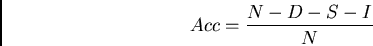
An additional ``relative features'' test is provided in the results.
For this test, absolute  position is removed from the feature
vector. This provides a sense of how the recognizer performs
when only relative features are available. This may be the case
in daily use since the signer may not place himself in the same location
each time the system is used.
position is removed from the feature
vector. This provides a sense of how the recognizer performs
when only relative features are available. This may be the case
in daily use since the signer may not place himself in the same location
each time the system is used.
| experiment | training set | independent | |
| test set | |||
| all features | 94.1% | 91.9% | |
| relative features | 89.6% | 87.2% | |
| all features & | 81.0% (87%) | 74.5% (83%) | |
| unrestricted | (D=31, S=287, | (D=3, S=76, | |
| grammar | I=137, N=2390) | I=41, N=470) |
The 94.1% and 91.9% accuracies using the part-of-speech grammar show that the HMM topologies are sound and that the models generalize well. However, the subject's variable body rotation and position are known to be a problem with this data set. Thus, signs that are distinguished by the hands' positions in relation to the body were confused since the absolute positions of the hands in screen coordinates were measured. With the relative feature set, the absolute positions of the hands are be removed from the feature vector. While this change causes the error rate to increase slightly, it demonstrates the feasibility of allowing the subject to vary his location in the room while signing, possibly removing a constraint from the system.
The error rates of the ``unrestricted'' experiment better indicate where problems may occur when extending the system. Without the grammar, signs with repetitive or long gestures were often inserted twice for each actual occurrence. In fact, insertions caused more errors than substitutions. Thus, the sign ``shoes'' might be recognized as ``shoes shoes,'' which is a viable hypothesis without a language model. However, a practical solution to this problem is to use context training and a statistical grammar.
For the wearable computer view experiment, the same 500 sentences were collected by a different subject. Sentences were re-signed whenever a mistake was made. The full 500 sentence database is available from anonymous ftp at whitechapel.media.mit.edu under pub/asl. The subject took care to look forward while signing so as not to confound the tracking with head rotation, though variations can be seen. Often, several frames at the beginning and ending of a sentence's data contain the hands at a resting position. To take this in account, another token, ``silence'' (in deference to the speech convention), was added to the lexicon. While this ``sign'' is trained with the rest, it is not included when calculating the accuracy measurement.
The resulting word accuracies from the experiment are listed in Table
4.3.
In this experiment 400 sentences were used for training, and an
independent 100 sentences were used for testing. A new grammar was
added for this experiment. This grammar simply restricts the
recognizer to five word sentences without regard to part of speech.
Thus, the percent correct words expected by chance using this
``5-word'' grammar would be 2.5%. Deletions and insertions are
possible with this grammar since a repeated word can be thought of as
a deletion and an insertion instead of two substitutions.
| grammar | training set | independent | |
| test set | |||
| part-of-speech | 99.3% | 97.8% | |
| 5-word sentence | 98.2% (98.4%) | 97.8% | |
| (D = 5, S=36, I=5 N =2500) | |||
| unrestricted | 96.4% (97.8%) | 96.8% (98.0%) | |
| (D=24, S=32, | (D=4, S=6, | ||
| I=35, N=2500) | I=6, N=500) |
Interestingly, for the part-of-speech, 5-word, and unrestricted tests, the accuracies are essentially the same, suggesting that all the signs in the lexicon can be distinguished from each other using this feature set and method. As in the previous experiment, repeated words represent 25% of the errors in the unrestricted grammar test. In fact, if a simple repeated word filter is applied post process to the recognition, the unrestricted grammar test accuracy becomes 97.6%, almost exactly that of the most restrictive grammar! Looking carefully at the details of the part-of-speech and 5-word grammar tests indicate that the same beginning and ending pronoun restriction may have hurt the performance of the part-of-speech grammar! Thus, the strong grammars are superfluous for this task. In addition, the very similar results between fair-test and test-on-training cases indicate that the HMM's training converged and generalized extremely well for the task.
The main result from these experiments is the high accuracies themselves, which indicate that harder tasks should be attempted. However, why is the wearable system so much more accurate than the desk system? There are several possible factors. First, the wearable system has fewer occlusion problems, both with the face and between the hands. Second, the wearable data set did not have the problem with body rotation that the first data set experienced. Third, each data set was created and verified by separate subjects, with successively better data recording methods.
The experiments above suggest that the first person view provides a valid perspective for recognizing sign language gestures. While it can be argued that sign language evolved to have maximum intelligibility from a frontal view, further thought suggests that sign may have to be distinguishable to the signer himself - both for learning and to provide control feedback. Extending the argument, more every day gestures should be recognizable by a camera placed at the point of view of the wearer. An interesting experiment would be to routinely blindfold a student learning sign language or other gestural task and compare the variation in motion to when the student is sighted.
As shown by the effects in the first experiment, body and head rotation can confound hand tracking. However, simple fiducials, such as a belt buckle or lettering on a t-shirt, may be used to compensate tracking or even provide additional features. Another option for the wearable system is to add inertial sensors to compensate for head motion. In addition, for ASL, electromyogram (EMG) sensors may be placed in the cap's head band along the forehead to analyze eyebrow motion based on muscle activation as has been discussed by Picard [161]. In this way facial gesture information may be recovered.
As the system grows in lexicon size, several other improvements may be made to handle the increased complexity:
In the above experiments, we have not addressed the problem of finger spelling. Changes to the feature vector to address finger information will be vital, but adjusting the context modeling is also of importance. With finger spelling, a closer parallel can be made to speech recognition. Three unit (tri-sign) contexts occur at the sub-word level while grammar modeling occurs at the word level. However, this is at odds with context across word signs. Can tri-sign context be used across finger spelling and signing? Is it beneficial to switch to a separate mode for finger spelling recognition? Can natural language techniques be applied, and if so, can they also be used to address the spatial positioning issues in ASL? The answers to these questions may be key to creating an unconstrained sign language recognition system.
While the camera cap was attached to an SGI or video tape recorder for development, current hardware allows for the entire system to be unobtrusively embedded in the cap itself as a wearable computer. For instance, the brim or front surface of the cap can be made into a relatively good quality speaker by lining it with a PVDF transducer (used in thin consumer-grade stereo speakers). Initial experiments show that this is feasible for relatively quiet areas. A smaller, matchstick-sized Elmo QN401E camera could be embedded in the front seam above the brim. Finally a computer, similar in concept to an uncased Lizzy, could be placed at the back of the head. However, given that such hardware is feasible, what might be the interactions between the user and the apparatus?
While this system is preliminary, as evidenced in the questions above, I can make educated guesses as to how such a system might be developed and used based on previous work in the speech community, drawing on the interaction survey provided by Schmandt [56]. First, though, the problem must be suitably constrained for an intelligent discussion. There are three classes of signers a sign language to English translator might assist: those who are deaf, those who are mute, and those who have a combination of handicaps. For a complete system, users from the first and last class must also have a method for understanding responses from their conversational partners, though this is beyond the scope of this thesis. In addition, while the methods and apparatus must be adjusted depending on the needs of the specific user, this discussion will remain at a higher level, showing a range of options that can be adapted as necessary.
A question that must be asked of an enabling technology is ``Will the resulting tool be passive or active?'' In this case, a passive translator would allow the user to sign normally, without any consideration to the apparatus. Its use would be transparent to the signer. Correspondingly, sign language recognition for such system would be very difficult due to a lack of constraints. If, instead, the translator is used as a tool that is actively maintained by the user, many more accommodations can be made for technological limitations. The signer has a mental model of the tool's use and limitations and acts accordingly. It is this later type of system that is of interest. To narrow the discussion further, we will assume the system is user dependent, has a sensing apparatus similar to that discussed above, and has access to a suitable ASL to English machine translator and English synthesizer.
As with speech recognition, no sign language recognition system can be made without addressing recognition errors. While tuning of the recognition system can change the relative amounts of insertion, substitution, and deletion (also referred to as rejection) errors, no amount of tuning will eliminate all errors. However, the task itself can be designed to minimize errors through:
A simple example of controlling the vocabulary is to eliminate signs that are hard for the system to distinguish. For example, compound signs, signs with intricate finger positioning, or signs with motion outside the camera's field of view might be removed from the working vocabulary. Since HMM-based systems work better for larger ``utterances,'' the vocabulary could be restricted to the longer variants of signs with similar meanings. A more extreme version of this methodology is to design the system for phrase recognition. In such a system, the user is restricted to a set of standard phrases, perhaps with slots for proper nouns. A less constrained system would allow any word as long as it followed a particular language model, such as the grammars described in the experiments above. Finally, different vocabularies or language models could be applied depending on the signer's context. This ``subsetting'' practice limits the complexity of the recognition problem [56].
A mobile vision system often has difficulty due to variations in the environment. However, with a cooperative user, some constraints might be met. For example, the signer might always face forward and sign with no head tilting so as to provide a relatively stable view for the cap-mounted camera. The cap might be custom fit to the signer's head to prevent slipping. The cap might also contain specialized light sources, such as near-infrared light emitting diodes (LED's) to compensate for the variable lighting inherent to mobility [237]. Similarly, the signer might wear specially colored or retroreflective gloves to aid tracking. In addition, the signer might wear clothes that interfere the least with hand tracking. Finally, since the color of the floor and the environmental lighting can severely impact tracking, the system might sample the environment continuously and provide a tracking quality indication to the user through a visual or auditory cue. This explicit feedback gives the signer the option of physically moving or changing the environment to aid the translator.
Possibly the most effective way to avoid errors is to train the signer himself, both in how to use the system and in what might be expected from the system. For example, the signer should sign consistently, with no embellishments, and with no head tilts. Even so, emotion, illness, or drugs such as caffeine may cause inconsistencies that are hard to model. Studies are needed to determine the amount of variance in sign that can be expected in everyday living. Perhaps one of the most pragmatic options to improve recognition is to create a ``push-to-sign'' system, similar to ``push-to-talk'' in speech [56]. In such a system, the signer indicates explicitly when the system should attend his hand movements for translation. This eliminates the very difficult task of trying to distinguish potential signs from other movements of the hands. A push-to-sign system could be implemented through a simple switch which the user holds during signing or presses to indicate the beginning and ending of an utterance [116]. Such a switch might be mounted in the signer's shoe [232], belt, wristwatch, or hat. Other methods for toggling recognition include a consistent head orientation or vocal command (for deaf users), These methods are ``out-of-band'' in that they do not use sign to indicate the command to recognize. However, another means is to design a special sign to toggle recognition. Such ``in-band'' signals to the recognizer must be easy to recognize and distinct from other signs that are to be recognized. Another variant is to precede each phrase with this special sign, such as the signing of ``computer'' in ``Computer, Yes I'd like to go to the movie.'' [183].
The usability of an ASL to English translator will depend heavily on how the system copes with recognition errors. The first issue is how such errors are detected. The system itself could identify errors by watching for strings of seemingly meaningless or out of context words. However, a more fruitful approach is to provide direct feedback to the signer. This may be done in a variety of ways. For a mute user of the system, the English spoken by the system provides an inherent check on the system's performance. If the user detects an error, he can indicate the error with a gesture to his conversational partner which doubles as a signal to the translator that an error occurred. Then, the user can try signing the same phrase again or try to reword his meaning such that the recognizer has a better chance of correct behavior. Of course, with a properly constructed interaction, the translator will use this additional information to improve its performance.
For a deaf user, a head-up display showing a continuous written English transcription seems appropriate. Such a display can provide feedback in a number of ways. First, the system can display the signs that were recognized as well as the English translation, revealing the entire system to the signer. In addition, the system can be designed so that the signer provides implicit confirmation for the translator. The user signs a phrase, the translator displays the signs and the English translation, pauses, and then begins to speak the translation. A ``completion'' bar runs underneath the translation to indicate the position of the speech synthesizer as it speaks. For a deaf user, such feedback is crucial so that the signer knows when to expect a response or continue. The signer can interrupt the system at any time (how this interruption occurs is a topic covered later). By interrupting the system during the initial pause, the signer indicates that the entire phrase is incorrect or too mangled to fix quickly. In such a case, the signer simply re-signs the phrase. However, if only one word is incorrect, the signer may wait until the synthesizer reaches that point in the phrase to interrupt and correct it. Finger spelling might be used instead of the word sign to help avoid ambiguity. Such a ``repair'' mechanism [56] may be extremely useful when specifying proper nouns that may not be part of the translator's normal vocabulary. Knowing this limitation, the user may sign a place holder sign as part of the sentence and then fill in the proper name as a correction as the synthesizer speaks the English translation.
Note that the repair mechanisms described so far have avoided complicated editing dialogs with the user. This policy helps maintain a certain conversational speed so that the receiver in the conversation does not get frustrated. The absolute minimum tolerable rate for a communication aid is three words per minute (wpm), and the impatience of the receiver is strongly inversely proportional to the rate at less than nine wpm [42]. However, expressive communication through handwriting can range from 15 to 25 wpm [195]. In addition, the author's informal tests with experienced users of the Twiddler one-handed keyboard show that rates of 30-60 wpm can be achieved. For comparison, typical speaking rates range from 175 to 225 wpm, and reading rates are typically 350-500 wpm [56]. Thus, the translator should exceed an average rate 15 or 30 wpm at the minimum to be faster than a mobile mute user writing or typing on a notepad or PDA screen respectively. For more compound handicaps, a goal of over nine wpm is appropriate. Of course, the true goal is to reach normal conversational sign speeds, which are approximately equivalent to spoken conversation [98].
At 15 wpm, the complete ASL to English translation loop needs to produce a word every four seconds on average. Thus, an explicit editing cycle with the user is possible. For example, after the user signs a phrase and the system displays the recognized sign and possible transcription, the signer may choose to edit a sign or English word before the synthesizer speaks the result. Again, in-band or out-of-band signals may be used to select the desired word from the transcription on a head-up display. In-band signals may include specially designed signs for editing, similar in style to the editing gestures used in today's pen-based systems. First the user must select the word for editing using gestures for scrolling forward or backward in the phrase just signed. After selection, the signer can make gestures for deleting or changing the word or inserting new words. Again care should be taken so that these gestures are distinct and not easily confusable with the expected sign vocabulary. To improve the speed of such editing, the recognizer may put ``tab'' marks over words that it has the least confidence are correct. These words may be selected via their recognizer scores, general a priori probability of occurrence in the vocabulary, or confusability with similar signs more appropriate to the current language context. By using a special editing gesture for this purpose, the user may move the editing cursor to these different words quickly. Similarly, the signer could use an editing gesture to indicate that he will ``point'' to the word to be edited. By extending his arm and finger, the user can indicate the position of the word relative to the left and right edges of the head-up display. Dwelling in a position for a second selects the word, and the user enters the editing mode. Of course, a flaw in this type of system is that the editing gestures themselves will have a certain probability of being recognized incorrectly. In addition, such gestures imply an additional learning cost to the system. However, a benefit to this system is that it does not require any additional interface hardware for editing.
In many cases, out-of-band signals will be more appropriate for the editing cycle. Out-of-band signals limit confusability with the recognition task and, in many cases, are faster for editing. Devices such as mousepads or trackpoints may be used to select the word to be edited. These might be mounted on the belt, wrist, or finger as a ring. However, since the hands and arms are used for signing, cursor control would best be delegated elsewhere. One can imagine many sorts of esoteric interfaces, ranging from toe to tongue switches. Each may have its advantage for a particular set of handicaps. However, with a head-up display and a limited number of targets (in this case, words) on the screen at a given time, an eye-tracker may be appropriate for selecting the word to be edited [204]. Simply dwelling on the word selects it. A range of words might be indicated by selecting first the word at the beginning and then the word at the end of the phrase. The user then signs or finger spells the word or phrase that should replace the selected word or continues to fixate to indicate that the word should be deleted. Similarly, simple editing controls might be rendered on the display. These controls could be selected by fixating (or pointing) on them. Besides ``delete,'' ``insert,'' and ``say it,'' a ``try again'' control might be made available. This latter control would replace the selected word or phrase with the next most likely word or phrase from the recognizer's scores. By displaying the ``next best'' list for each word or phrase as it is selected, the user can quickly determine if this action is appropriate.
So far, we have ignored the implications of the editing process to the social process of the conversation. Already, the synthesized nature of the translated speech and the delay between the sign and resulting spoken translation will skew the normal cues conveyed in the cadence of a spoken conversation [83,164,45,46,27]. If the editing process is not made explicit to the receiver in the conversation, the eye motions, additional gestures, or actuation of pointing devices could cause additional distractions. Thus, detailed studies are necessary to determine if such editing interfaces are suitable to the task both technically and socially. For example, would it be more acceptable socially for the signer to perform editing on a pen-based tablet? Is the social gain worth the slow down in conversational speed that results from having to stop signing and dedicate the hands to the pen interface? On the other hand, are eye trackers or other pointing devices accurate and comfortable enough? Does the editing process itself take too much time compared to simply re-signing the word or phrase? Does the editing process detract too much from the conversation, both for long-term and short-term use? This line of questions leads to a higher level of inquiry. How many errors can be expected with the translator? How significant are the errors to communication? Is the context surrounding the error sufficient to recover the true meaning of the phrase?
A way to experiment with the ideas presented in this discussion without requiring additional technological developments is to run a ``Wizard of Oz'' simulation similar to those of Gould [81] for speech recognition based typewriters. Using the wireless apparatus described in Chapter 2, video from the signer's cap camera would be transmitted to a remote expert who would recognize the sign. The remote expert's English translation would be transmitted back to the computer and head-up display in the signer's cap. The cap would then allow the user to edit the translation and synthesize the speech as appropriate. Note that such a system requires the remote expert to enter appropriate text for transmission back to the signer. This may be done via a keyboard or speech recognition depending on the speed and accuracy desired for the experiment. Unfortunately, the speed of a fully automated recognition system can not be emulated with this system. Also, such a system would not eliminate errors, since even an expert translator would make occasional mistakes in translation or transcription. However, such errors enforce the need for experimentation on potential repair methodologies and apparatus. In fact, the transmitted video may be degraded on purpose to force the use of repair strategies by the signer. In this manner, the simulation of the actual task can drive the development of the technology.
From the ASL experiments, we've seen a successful demonstration of the vision architecture and tools presented in Chapter 2. In addition to providing a concrete demonstration that complex gestures can be recognized by a wearable system, the ASL experiments show how the HMM framework can model user action. At the lowest level, the HMM's provide a stochastic means of modeling actions with multiple states. Models of expected user behavior can be layered on top of this in the form of context and statistical grammars. These higher level models can improve recognition as well as predict the user's next action by providing priors on action co-occurrences. Such predictive ability may be used in other systems to pre-load necessary resources or to arrange options in an interface for rapid selection [71].
While the ASL system is explicitly controlled by the user's actions in that the signer gestures and expects a response from the computer, the interface operates on a more abstract level than traditional interfaces. For example, when the system is demonstrated for real-time ASL to English translation, word order changes in the translation, and there may not be a one-to-one mapping of gestures to spoken words (this is due to the different sentence structure between the two languages). Secondly, in some of the experiments, recognition can depend on surrounding gestures. This certainly contrasts with the directness of today's point and click interfaces!
Since the cyberpunk sub-genre of science fiction began [78,223,222], readers have been fascinated by the dual ideas of a physical world annotated with active virtual information and the automatic collection and logging of personal experiences. What many never realize is that these ideas have roots in some of the earliest computer research. Vannevar Bush's ``Memex'' paper ponders the future use of a head mounted camera and computer system that records a scientist's experiments, logs his searches through the literature, and reproduces these trails of thought on demand [25]. Sutherland's 1968 ``Sword of Damoscles'' tracked the user's head and rendered appropriate rotated virtual objects in a head-up display [227]. Also in 1968, Engelbart showed the principles of hypertext and interactive sharing at the Fall Joint Computer Conference [55].
Practical augmented reality (AR) systems have begun to appear recently. Some are designed to provide an augmented environment in a particular area, such as a room [111,249]. The majority of systems that use head-up displays still tether the user to bulky equipment (see Azuma's [9] or Vallino's [238] works for a review of AR systems). However, some systems look toward the mobility needed for everyday, personal use [172,146,199,214,62,231]. Generally, AR systems either concentrate on precise tracking for visual registration of graphics or interfaces with the physical world [151,35,236,102,65,121,82,103,72,125,220,34,109], or they use less precise tracking methods to create fields of activation for graphics, text, audio, or haptics [61,63,64,231,104,121,17,187,57,38,217]. These systems may be further subdivided into using primarily electromagnetic, infrared, and GPS [109,61,63,64,65,72,125,231] or computer vision [151,35,236,102,121,82,103,220,34] tracking systems. Much of the work presented here was first performed and documented in 1995 [213] and was inspired by earlier projects by Feiner et al. with electromagnetic trackers [63,64,61]. However, the systems below are closer in implementation to the those pursued concurrently by Rekimoto and Nagao [172,146] for approximate registration or Cho, Park, and Neumann [35] for precise overlays using fiducials.
While this chapter will demonstrate systems that use precise registration normally associated with augmented reality, it will also describe a system that runs in the background of the user's attention, hinting at information that the user can access if desired. This sort of serendipitous interface extends the principles of the previously discussed Remembrance Agent to the physical world. Most systems presented in this chapter were prototyped with the wireless video transmission system but could now be run on a self-contained wearable using a combination of general-purpose and custom hardware.
FingerTrack is one of my earliest and simplest augmented realities using the vision architecture [212]. FingerTrack allows the user, wearing a head-up display and head-mounted camera pointed forward, to use his finger as his mouse pointer (see Figure 5-1). The user places a small colored thimble at the end of his finger to aid tracking or, if the background does not contain too many skin-colored objects, simply uses his unadorned finger. The FingerTrack module outputs the location of the user's fingertip to the XFakeEvents module which places the computer's pointer at an appropriate location on the user's display. Thus, the system provides the illusion of the mouse pointer following the user's fingertip. Mouse button clicks are still controlled by a keyboard, but it is not hard to imagine extending the system to recognize hand gestures, such as extending the thumb, to indicate a mouse button click. This system was designed to explore an early criticism that my wearable lacked a sufficiently easy method for drawing as compared to the pen systems of the time. This system, and a similar system prototyped using the ALIVE environment [249], seemed immediately understandable and intuitive to traditional computer users who used the systems informally. Note that once the system's pointer is controlled by the user's finger, any application using that windowing system can be controlled in the much the same manner. For example, Mann [131] shows how such a system can be used for precise outlining of real-world images using a drawing program similar to the one shown in Figure 5-1.
Millions of Americans suffer from a loss of sight that can not be corrected with normal optical methods, and several attempts have been made to use head-mounted cameras and electronics to help compensate for this handicap [198,40,224]. One such attempt by Johns Hopkins University [134] inspired this project with Steve Mann in early 1995 [214]. At the time, the existing work had produced a head-mounted display and camera system that could enhance the brightness and contrast of the incoming image. This type of system can help some low vision sufferers; however, many more could be helped with a system that could arbitrarily re-map the visual field, which was, at the time, undemonstrated in a portable system. In re-mapping the visual field, areas from the input image are magnified, shrunk, or enhanced in relation to other areas in generating the output image. Such re-mapping can emphasize areas of the visual field in ways impossible with standard optical lenses. The image can also be re-mapped around a user's scotomas, or abnormal blind spots, in the retina. If we could create the appropriate re-mapping software on a workstation, we knew we could demonstrate a portable visual re-mapper through the wireless video transmission system. Thus, I developed the VisualFilter module of the vision toolkit described previously. This module allows the user to specify, using standard computer graphics concepts, explicitly how the input video image should be warped or manipulated when creating the output video image. Results can be seen in Figure 5-3, which shows how the technique can be used to map around scotomas, and Figure 5-2, which shows how text can be magnified by applying a simple 2D Gaussian coordinate transformation [214]. The latter transform allows individual letters to be magnified so as to be recognizable while still providing the context cues of the surrounding imagery. While any user would need to stay within the range of the wireless transmission unit, the system could allow immediate experimentation and prototyping.
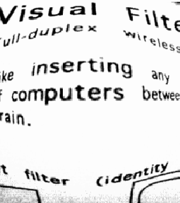 |
Coincidentally, soon after this project was demonstrated, the author's grandmother, Ruth Marshall, developed giant cell arteritis and was told she would never be able to read again. At the time, the base station for the video re-mapping was an SGI Onyx which meant that the system was too large and expensive to dedicate to a personal project. However, a simpler desktop unit which adjusted brightness, contrast, magnification, and color allowed Mrs. Marshall to be independent with her reading and writing (see Figure 5-4). Her unit was used for three years and has inspired the creation of similar devices based on the directions published on the MIT Wearable Computing Web Page. With time, Mrs. Marshall's disease progressed, but the more advanced system, now reproduce-able using any SGI O2, was not tested due to Mrs. Marshall's failing health.
Museum exhibit designers often face the dilemma of balancing too much text for the easily bored public with too little text for an interested visitor. With wearable computers, large variations in interests can be accommodated. Each room could have an inexpensive computer embedded in its walls, say in a light switch or power outlet. When a visitor enters the room, the wall computer can wirelessly download museum information to the visitor's computer. Then, as the visitor explores the room, graphics and text overlay the exhibits according to his interests. Taking this example farther, such a system can be use to create a physically-based extension of the ``Web.'' With augmented reality, hypertext links can be associated with physical objects detailing instructions on use, repair information, history, or information left by a previous user. Such an interface can make more efficient use of workplace resources, guide tourists through historical landmarks, or overlay a role-playing game environment on the physical world. Early implementations of these concepts have been shown using electromagnetic trackers, GPS units, and electronic compasses [61,62,231], but more recent systems have begun to use computer vision to similar effect [35,103].
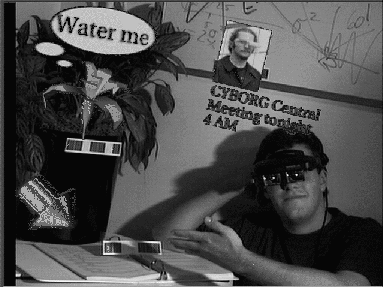 |
In order to experiment with such an interface, the augmented reality video apparatus from Figure 2-8 was assembled and the TagRec module of the vision toolkit was developed. Visual ``tags,'' as shown in Figure 5-5, are attached to each active object to identify it uniquely. At run-time, the identity, position, zoom factor, and rotation of each tag is sent from TagRec to a graphics program, VirtualText, which composites appropriate text, 3D graphics, or movies on to the video image from the head-mounted camera. At start-up, VirtualText, originally written by undergraduate Ken Russell for the project, reads in a set of bindings for each tag that specifies the information object to be associated with that tag. In addition the bindings specify the rotation and scaling transform that relates how the virtual object should appear in relation to the tag. Information objects can include simple text strings, Open Inventor graphics objects, or a list of images to be concatenated into a movie. The result can be seen in Figure 5-5. A similar identification system has been demonstrated by Nagao and Rekimoto [146] for a tethered, hand-held system. This system has been extended into a full wearable design [172]. More recently, Cho et al. [35] have demonstrated ring fiducials which provide similar characteristics; in addition, these authors have analyzed the optimal sizes and separation distances for their fiducials.
Beginning in 1995, this system was used to give mini-tours of the laboratory space as shown in Figures 5-6 - 5-8. The purpose of this system was to create a virtually active space where pieces of equipment were annotated with information demonstrating the research projects for which they were used. Active LED tags are shown in this sequence from the original system, though subsequent versions used the paper tags exclusively for convenience. Whenever the camera detects a tag, it renders a small arrow on top of that object indicating a hyperlink (Figure 5-6). If the user is interested in that link and turns to see it, the object is labeled with text (Figure 5-7). Finally, if the user approaches the object, 3D graphics or a texture mapped movie are rendered on the object to demonstrate its function (Figure 5-8). Using this strategy, the user is not overwhelmed upon walking into a room but can explore interesting objects at leisure.
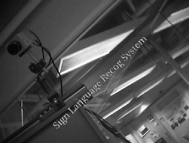 |
The Elmo MN401E camera fitted with a 7.5mm lens results in a visual field of view of approximately 55 degrees horizontally by 40 degrees vertically. If the incoming video is analyzed at 640 by 480 pixels, tags viewed from the front with good lighting can be correctly identified from 12 feet by the TagRec module described in Chapter 2. Normally, tags are oriented parallel to the floor so that their identifying code is read horizontally left to right. This takes advantage of the camera's larger field of view and number of pixels in the horizontal direction. If a tag is viewed from extreme angles, it becomes difficult to identify. The colored squares can become indistinct due the effects of foreshortening and perspective. Specifically, while each square is 0.875 inches across, it is separated from its neighbor by 0.125 inches. Thus, at sufficiently high angles or low resolution the boundaries of each square can be indistinguishable. For most situations, a tag is viewed from a maximum of 45 degrees horizontally from the tag's surface normal. Testing the system for these angles revealed that the system could identify tags from a distance of 9 feet. Similarly, for the laboratory tour, a tag is rarely viewed from more than a 45 degree angle vertically from the surface normal. Note from Figure 2-14 that the ``squares'' are actually rectangular, with a height of 1 inch to their width of 0.875 inches. This allows easier discrimination when the tag is rotated vertically in relation to the camera. Again, testing revealed that tags could be identified at nine feet in good lighting.
As noted previously, TagRec reports position and rotation of a tag even when it can not be identified. In fact, tags can be located at up to 15 feet when viewed along the surface normal and 11 feet when viewed from 45 degrees off the normal. A tag might be located and not identified due to resolution, rotation, specular highlights from glossy paper, or lighting colored such that the green squares are less visible than their red counterparts. VirtualText takes advantage of tag location without identity by rendering a generic arrow over the unidentified tag. This way the user may approach the tag if he is interested in its contents, and the increased resolution or change in illumination may allow TagRec to identify the tag.
Before each use, TagRec is calibrated to an example tag through user adjustable sliders. This thirty second process allows TagRec to obtain a model of the expected brightness and coloration of the tags in a particular environment. After calibration, TagRec proved very robust, rarely locating false tags or identifying tags improperly even in a laboratory filled with red furniture and trim. In addition, many tags can be located in the same area without difficulty. Often the author would demonstrate the system with very little notice, printing out new tags and binding text and graphics to them as appropriate for the incoming visitor.
With a brief explanation, otherwise uninitiated visitors adapted very quickly to the apparatus and the concept of physically-situated hypertext. Users naturally stepped toward an object to ``click'' on it. Later on, I began to mix smaller paper tags among the larger ones. A user would see information associated with the larger tag, step toward the associated object, and the system would recognize the half-sized tags in the local vicinity. This technique allows an intuitive presentation of levels of detail when annotating an environment.
Due to the complexity and number of the objects rendered, frame rates could be low. However, this gave a cartoon-like appearance to the overlays that may have set the user's expectations appropriately. Users recognized that they had to stay still if they wanted good registration with the overlays. In addition, the distinctive look of the paper tags gave the users an indication as to which objects would have information associated with them.
A problem with the AR system was the limited field of view of the head-up display and camera combination. Since the early systems were only slightly see-through, the graphics were overlaid on the video from the camera, and both were presented in the user's head-mount. The user was effectively seeing through the camera lens, limiting his view. Thus, the user had trouble moving rapidly and interacting with others in the environment. As display technology advances, this problem should improve. Another, unexpected problem was with the paper tags. At times, a set of tags and annotations would be remain deployed for several months. During this time the colored ink on the paper tags would fade, requiring that the user approach the tags more closely for identification. Of course, higher quality tags could be produced easily. A final problem was with the wireless video transmission units. When the user happened to position himself such that one of the video transmitter's antennae was perpendicular to the corresponding receiver, the video transmission would become noisy, sometimes triggering false tag positioning. Such problems will improve considerably with self-contained video analysis on the wearable.
When three or more tags are used on a rigid object, and the relative positions of the tags are known, 3D information about the object can be recovered using techniques developed by Azarbayejani [8]. Registered 3D graphics can be overlaid on the real object. Such registered graphics can be very useful in the maintenance of machinery. Extending a demonstration by Feiner [64], Figure 5-9 shows 3D animated images demonstrating repair instructions for a laser printer. The registration method becomes increasingly stable with additional known feature points. Since the tags have known dimensions, two feature points can be recovered for each tag: the right and left-hand sides. However, since precise registration implies the need for exact models of the annotated objects, this system was not used prevalently [214]. More recently, Levine [121] has extended the tag system to 2D visual tags which encode 32 to 128 bits of information in a seven by five grid of color squares. Due to the inherent planar structure of these tags, only one tag is needed to a align a 3D graphics overlay. However, for good registration, the tags must be relatively large in the camera's view.
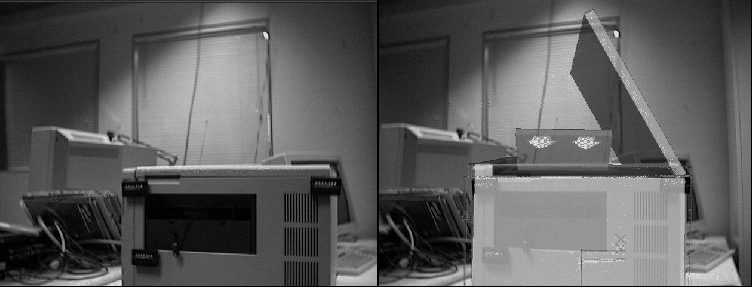 |
The visual tags shown in Figure 5-9 consist of the small LED alphanumeric displays. For expensive machinery such as an aircraft, a manufacturer may want to embed such tags to aid in repair diagnostics. Such displays may indicate error codes (similar to some of today's printers and copiers) that the technician's wearable computer can sense. Thus, appropriate graphical instructions can automatically overlay the user's visual field. In addition, active tags may blink in spatial-temporal patterns to communicate with the wearable computer or to aid tracking in visually complex environments [102]. Adding infrared or radio communications between the repair object and the wearable computer may allow more complicated cooperative diagnostics or repair instructions tailored to the user's level of expertise. Of course, the features of these more advanced systems must be weighed against the low cost of the passive tags discussed in the previous section.
One limitation of the system, of course, is the necessity of the tags for object identification. If a physical tag needs to be placed on each object to be annotated, the population of the world with hypertext links would be very slow. Instead, DyPERS [104] shows how the natural coloring of the objects themselves might be used for recognition using object recognition algorithms by Schiele [189]. However, both the tag recognition and this ``visual signature'' recognition systems are limited by how many objects they may distinguish. To avoid running out of identifiers or overloading the object recognition system, an additional sense of location is needed.
One method for providing location information is to use the Locust swarm discussed in Chapter 2. By listening to these IR beacons, the user's wearable computer can determine its location and load the appropriate set of annotations for the region. Since each Locust region is unique, tags can be reused from other regions. In addition, since the Locusts can act as local memory for their region, users can upload links to their own annotations of the environment. Such annotations may specify an association with a particular object (either tagged or recorded in the DyPERS object database) or with a given Locust's region. In addition, the annotation may be encrypted so that it will only be visible to a particular individual or group of individuals. Thus, users can leave location-based, encrypted ``Post-it'' notes or graphics for each other, extending the physical hypertext system [209]. Significantly, since the Locusts themselves are not networked even in upload mode, there is no remotely monitorable network traffic to reveal the presence of a user at a particular node. Thus, the Locust swarm protects its users from privacy attacks.
Another potential use of the Locusts is a ``sneaker net'' propagation of information. A particular information ``flea'' resides in the memory of a particular Locust. This flea may be an agent waiting to observe a specific event for a particular user, or it may be a resident of the local augmented reality, similar to the Julia program in multiple user dungeons (MUD's) [68]. When the flea decides to move from one Locust to another, it waits for a participating wearable computer user to pass under its current Locust. The flea examines the user's past path through the swarm of Locusts and determines if the user is going in the desired direction. If so, the flea downloads itself on to the user's wearable, waits until the user passes another Locust closer to its destination, and uploads itself to this Locust. In this way, the Locusts, even though they themselves are not connected to a network, can be used as a long term information propagation network. This method allows user annotations in a space to adopt behaviors and to migrate as appropriate over time.
At the time of this writing, the Locusts have been in use in two large areas of the Media Laboratory for over two years, and a simple annotation database has been constructed. Some Locusts have run almost continuously for that time period. In addition, Locusts have been adopted by several other laboratories around the world. Until recently, however, the Locusts have been used mainly for research and demonstrations. One problem was simply the number of serial ports available on the standard wearable computers of the time. Another problem was that the cellular wireless Internet service for wearable computer users, which allowed connection in most of the state of Massachusetts, was not very effective inside the laboratory. Thus, updates to the annotation database took considerable effort. However, research on these beacons continues, looking toward radio frequency versions, effective implementations of the concepts described above, and methods for integrating better tracking through triangulation, electronic compasses, and user modeling [76].
By recognizing and tracking physical objects, the wearable computer can assign computation to passive objects. The virtual version of the object maintained in the wearable computer (or on a wireless network) can then perform tasks on behalf of the user, communicate with other objects or users, or keep track of its own position and status. For example, the plant in Figure 5-5 may ``ask'' a passerby for water based on a time schedule maintained by its virtual representation. This method is an effective way to gain the benefits of ubiquitous computing [243] with a sparse infrastructure.
As originally stated, ubiquitous computing implies embedding processors in many everyday objects [243]. For the purposes of this discussion, this will be called the environmental approach. The environmental approach raises several technical problems - many of them interrelated. The most obvious issue is the cost of installing and maintaining the infrastructure. While computers, sensors, and microcontrollers may be made at extremely low cost in the near future, each device still has issues of power usage and communications. In order to keep the devices themselves low maintenance, environmental power recovered from heat differentials, solar energy, or radio may be used instead of batteries. A good example is passive radio frequency identification (RFID) tags which use the electromagnetic field of their readers to power a microprocessor and weak radio frequency transmitter that announces a unique ID [97]. However, such devices have a range of about one meter before the reader's field becomes ineffectual. In order for such devices to contact the rest of the infrastructure, a higher powered network must be used to retransmit information. Thus, maintenance has been moved from the individual devices to a network infrastructure which itself has issues of power and maintainence. Of course, batteries can be included with each device to extend their networking range and functionality. Some of today's microprocessors can run for several years on a lithium tab cell. However, the longer the distance such a device has to communicate wirelessly, the more power it will require. Unfortunately, including a battery constrains the size of the device and significantly increases its cost. In addition, if an average house contained 300 such devices whose batteries lasted one year, the user would have to change a battery almost every day. While technology will improve the characteristics of embedded devices, there will always be trade-offs between cost, maintenance, functionality, power, and networking.
One of the most fundamental issues in ubiquitous computing is privacy. For a history of privacy and implications of its violation, the reader should refer to an assortment of references [194,244,137,201,142,180]. Technological infrastructure can be used to violate privacy if checks and balances are not designed into the system. A good example is the indoor location systems that work through ``active badges'' [191,241,114,193]. In these systems, the badges continually announce their presence to the environment which then, through a wired network, report the location of the badge to a central system.
Active badge systems suffer from user perceptions that the infrastructure is used for ``spying'' [16]. While the badge system may be very useful for opening locked doors automatically, might it not also be used to time a trip to the restroom? While a concerned badge wearer can certainly take off the badge at any given instance, the aggregate information collected over several days or months can still reveal patterns of behavior.
Technically, active badges can be made secure. A badge system can use current encryption technology such that only a master operator or security guard has access to the descrambled signature from a given badge. However, this master operator might be bribeable or might be manipulated to reveal information without realizing it. Rothfeder [180] shows how such ``social engineering'' can be used repeatedly to gain sensitive information. In addition, any such central database is vulnerable to legal subpoenas.
Suppose that the above concerns are addressed through technology and policy. An active badge system is vulnerable to yet another attack. This attack simply monitors the amount of traffic from the various badge receiving stations. While specific user information might not be obtained, data on how many people are in a given area or the path of some person through the building might be determined.
Similar attacks can be used on the wireless infrastructure associated with the environmental approach to ubiquitous computing. However, the systems outlined above suggest another approach, that of concentrating the infrastructure on the user. With a wearable computing approach, the user carries as part of his clothing a relatively powerful CPU, a large hard disk, interface peripherals, networking, and batteries. By concentrating the hardware in one place, failures are recognized and corrected quickly, only one set of batteries needs to be maintained, implementation can be immediate instead of waiting for the development of infrastructure, and networking is concentrated through one gate. This last point is the most important and one of the fundamental design principles of wearable computing: the user should control his own ``bits.'' In other words, any data sensed about the user, whether it be his location or heart rate, should have to go through the user's wearable computer. In this way the user has control over the degree of functionality he uses versus how much information he wants to reveal about himself.
For example, with the active badge location systems described above, the user has very limited control over who or what knows his location. The user has a simple binary choice, to wear the badge or not, and, as stated previously, the act of taking off the badge itself is an information source. With beacon architectures such as GPS or the Locust, the surrounding infrastructure has no way of recording or sensing the user unless the user chooses to reveal himself. However, unlike active badge systems, even if the user choses to remain undetected, his wearable computer can utilize the positioning signals for its interface, user diaries, etc. If the user chooses to reveal his location, he can limit who sees this information. For example, the user's wearable computer can run an information service, similar to Unix's finger command, that checks to see who is requesting the information before returning it. While identity forging and traffic attacks are still a danger, the wearer has the choice to provide the service or not based on his perception of the situation.
RFID tags offer another model for the wearable computing approach. Instead of requiring batteries and large scale network capability for each sensor in the room, the wearable computer can create an electromagnetic field to power the sensor, similar to current passive RFID readers [97]. Any information the sensor wants to communicate is sent to the user's wearable computer, out of necessity, for retransmission using the wearable's more powerful networking hardware. In this manner, the user again has control over what information is rebroadcast about him. In addition, the wearer knows a sensor can not be active unless he, or another user, is physically near it. While such a sensor could be wired into the room's network as well, it would require significantly more effort to install and be relatively easy to detect. Thus, sensors that require an off-body viewpoint can be utilized without necessarily revealing information to the environmental infrastructure.
Using the methods outlined above, a wearable computer can determine its location and recognize objects in its environment without revealing its presence to the environment. From this sensing capability, the wearable can assign complex virtual behaviors to physical objects or locations. Simple examples include a counter displayed for each time the user looks at a particular object, reminders for procedures for complex machinery, and messages or tips left by colleagues. However, if the wearer chooses to reveal more information, more functionality is possible.
To extend an example often used in the Things That Think consortium when talking about ubiquitous computing, the wearable computer can sense that its user is heading toward the company's gym after a long night of work. The wearable predicts its user will want coffee afterward and tells the local coffee machine to begin brewing. If the user instead drinks tea, the waste from the error, i.e. unused coffee, is not severe. However, if the prediction was correct, the wearable may save his user several minutes. Note that the coffee machine does not necessarily need to know the identity of the user. Instead the user's wearable computer can maintain a key that unlocks the coffee machine's capability. Network routing can be designed such that it is not possible to backtrack the request to the user's computer. Thus, the only information that can be logged by a ``corrupted'' coffee machine is that a request was made at a particular time.
A more powerful example involves advertising. As the wearer walks down a New York City avenue, a billboard advertising jeans begins transmitting information to the user's wearable computer. The wearable computer conveys that its user has all but the most interesting advertising overlays turned off, and the billboard begins a negotiation process for the user's attention. After asking the wearable the user's pants size, the billboard hooks into the supplier's local inventory and discovers that they have an overstock in that size. The billboard offers its product at a discount. The new price causes the wearable computer to whisper the offer discretely in the user's ear. The user, now interested, turns to see an animated advertisement tailored to his interests overlaid on the billboard. Deciding that the product is worth the price, the user commits to the purchase and the wearable computer transfers money and exchanges address information with the billboard. The billboard reroutes an express delivery truck to drop off the jeans at the wearer's house within the next two hours. Obviously, this form of just-in-time information delivery can provide very powerful tools for the retail, advertising, and delivery industries.
Note that, although this example involves a tremendous exchange of information, the user had explicit or implicit control of the transaction at all times. The user could have set his wearable computer to ignore all transmissions. Similarly, the user's wearable computer might have learned from previous evening strolls that this is a meditation time for its wearer and automatically ignores all but the most urgent transmissions. The wearable computer might be set to ignore solicitations from advertisers or only display their offers without any return communication. On a finer level, the user could tell his wearable to communicate with advertisers who offer products on his shopping list. Finally, the user could have directed the billboard to have the jeans delivered to the local retail outlet where he would purchase them in cash, thus not revealing his credit card number, name, or address to the advertising agency.
This chapter discussed several augmented reality interfaces developed with the vision toolkit. In addition, this chapter explored using wearable computers as an approach to ubiquitous computing and contrasted this to an environmental sensing approach. The first of these interfaces involved sensory augmentation and direct control by the user. However, the physically-situated hypertext project demonstrated how a wearable computer, through tracking its location and attending the objects of interest for the user, may provide information based on the user's current physical environment. This information may be in the form of reminders or serendipitous links that the user can follow at leisure. Much of the work presented in this chapter demonstrates perceptual techniques and suggests interfaces for the future. However, as this equipment becomes less obtrusive and easier to wear, the wearable computer can examine patterns of use throughout the day and adapt its interface appropriately. The next chapter describes an application domain where the computer interface is very much secondary to the user's primary task, and modeling the user's actions is crucial to the suggested interface.
Chapter 4 describes a system that analyzes gestures designed for communication, namely sign language. That project is directed toward the creation of an interactive tool, where the user is aware of the computer and its task, and the user may modify his natural behavior willingly to help the computer perform its task. Chapter 5 describes an interactive augmented reality in which the computer renders hypertext links on the physical world that the user can explore simply by approaching the linked object. While the computer may supply serendipitous information based on the user's current environment, the user directs the computer explicitly once a link of interest is discovered. This chapter discusses a class of problem that is often more difficult, in which the computer recovers useful information when it is a passive observer of user behavior. Specifically, we will attempt to recover the location and current actions in a player of a ``paintball-like'' game using only on-body sensors. This ``fly on the wall,'' or in this case, ``fly on the forehead'' approach to user perception is particularly difficult.
User location may provide valuable clues to the user's context for an information assistant [153,114,209,191,126,193,157,241]. For example, if the user is in his supervisor's office, he is probably in an important meeting and does not want to be interrupted for phone calls or e-mail except for emergencies. By gathering data over many days, the user's activities throughout the day might be modeled. This model may then be used to predict when the user will be in a certain location and for how long [156]. Such a model might be used, for example, for intelligent network caching based on when the computer expects the user to be within range of his wireless network [185].
Most ubiquitous and wearable computing systems that try to observe and model user location indoors use infrared beacons or radio receivers [153,114,209,191,126,193,157,241]. Such systems require more units to cover new territory or to add precision. This increased infrastructure implies increased installation and maintenance costs. Instead, ``DUCK!,'' or ``Distributed Ubiquitous Combat Knowledge, Bang,'' attempts to use computer vision from cameras on the player's body for the same task. While location recovery is significantly more difficult, this method avoids the complications and costs of off-body infrastructure.
Mobile robots also use computer vision for navigation [93,99,170,94,235,135], but most combine this sense with the manipulators or feedback systems of the robot. For example, by counting the number of revolutions of its drive wheels, a robot maintains a sense of its travel distance and its location based on its last starting point. In addition, many robots can close the control loop in that they can hypothesize about their environment, move themselves or manipulate the environment, and confirm their predictions by observation. If their predictions do not meet their observations, they can attempt to retrace their steps and try again. Since the DUCK! hardware simply observes the user's environment with no direct control or feedback, it is at a severe disadvantage in determining location compared to traditional mobile robots.
By identifying the user's current actions, a computer can assist actively in the current task by displaying timely information or automatically reserving resources that may be needed [64,196,214]. However, a wearable computer might also take a more passive role, simply determining the importance of potential interruptions (phone, e-mail, paging, etc.) and presenting the interruption in the most socially graceful manner possible. For example, while driving alone in an automobile, the system might alert the user with a spoken summary of an e-mail. However, during a conversation, the wearable computer may present the name of a potential caller unobtrusively in the user's head-up display.
DUCK! tries to interpret the player's actions, namely shooting, reloading, and ``other,'' from observing his hands. Unlike the ASL project, in which each gesture has a pre-defined meaning that the user expects the computer to identify, the gestures in DUCK! are spontaneous and are natural artifacts of the game. Previous research has attempted to recognize naturally-occurring gestures [248,30] or gestures relating to the control of virtual or physical objects [225,20,196], but these projects often require datagloves or controlled situations. The DUCK! environment, on the other hand, is natural, harsh, highly mobile, and constantly changing. In many senses DUCK! is a planned departure from laboratory experiments, testing the techniques from the previous chapters in a difficult environment where the user has no sense of cooperating with the computer but is engrossed with the primary task of not being shot!
While the perception and modeling performed in DUCK! are directed toward creating a particular style of interface for the player in the future, current hardware and personnel limitations prevent even the simulation of the interface during an actual game. Instead, sensor data is stored on-body and processed off-line. Using this data, a possible future interface is constructed and discussed with an expert Patrol player who is otherwise naive regarding the project.
Patrol is a game, similar to paintball, played by MIT students every weekend in a campus building. While Patrol games can have over forty participants, sixteen players divided into four or five teams is more typical. Game play lasts three hours, and the playing field is limited to the mezzanine and first floors of the building. Participants are divided into teams denoted by colored head bands. Each participant starts with a rubber suction dart gun and a small number of darts. During the game, players must recover used darts to replenish their supply. Guns can fire only one shot before reloading and have a maximum range of ten meters. At the start of the game, the players disperse and hunt members of other teams. When shot with a dart, a player removes his head band to indicate his temporary removal from game play and runs to the second floor to ``resurrect'' before returning to the game. While ``dead,'' players are strictly forbidden from interfering with game play or revealing information about the current positions of teams to ``alive'' players. The process of resurrection is designed as a penalty for being shot and helps insure that the player will not have time to return to the same skirmish. For the purposes of this discussion, a skirmish will be defined as an active exchange of darts between players for the control of a particular area. Most skirmishes last under a minute. In general, game play is rapid, with players resurrecting up to 100 times. When possible, many players prefer to work together as a more effective fighting force, using strategies somewhat similar to those of small military units searching buildings occupied by hostile forces. Success in a skirmish often involves a combination of stealth, skill, speed, experience, and real-time coordination between teammates.
Patrol is designed with a careful system of checks and balances evolved over a decade of game play. For example, the time it takes a player to reload his gun helps maintain the pace and strategies used in the game. In the past, technological improvements of the game's weaponry have skewed game play, resulting in the outlawing of any gun that is not a spring-loaded, single-shot rubber dart gun. However, improvements in team communication and strategy are tolerated as interesting novelties. Thus, this project examines how the techniques from previous chapters might be adapted to create an automated assistant for team play in Patrol. The use of on-body computer vision for determining a player's location and actions are of particular interest, since such systems might be useful for analyzing more everyday activities [114,191,157,241].
The Patrol environment consists of 14 strategic areas: front stairs, lobby, front hall, neutral, front tutorial room, back tutorial room, T junction, front classroom, back classroom, mezzanine hall, mezzanine stairs, mezzanine, back hall, and back stairs. Figure 6-1 illustrates these areas and their unique two letter designations used for annotating the video test data. With the exception of a long corridor consisting of parts of the lobby, front hall, T junction, and back hall, the areas of the Patrol environment are separated by doorways blocked open for game play. The playing field is remarkable for the number of possible routes between areas. However, from repeated exposure, even novice Patrol players become intimately aware of the playing field quickly.
During a typical game, team members are scattered in these areas, and finding team members is difficult without alerting enemy teams to one's location. Occasionally, team members shoot each other by mistake. In addition, when working alone, a player will stumble across another team, fire and miss, and run in the opposite direction yelling the opposing team's color while reloading. The player does this in the hope that one of his teammates will recognize his voice, determine both his and the opposing team's location by the sounds of the skirmish, and be able to provide support. Often this impromptu coordination effort fails as teammates do not have time to reposition themselves or misjudge the locations of the enemy players. In addition, such behavior brings other enemy teams who prey opportunistically on the confusion.
When resurrecting, a player often does not know which parts of the playing field his teammates currently hold. In addition, he does not know his team's current activities. Team members may be holding territory in a stand-off with another team, waiting for reinforcements, redeploying, resurrecting, or in a current skirmish. If the player had a better knowledge of his team's deployment and current activities, he would know where he is most needed and adjust his route, speed, and stealth to adapt to the situation. Such an ability would change strategy significantly for any team who had such an advantage.
The simplest example is when multiple team members are resurrecting at approximately the same time. Since there are multiple paths to the second floor, team members are often unaware of each other. Having knowledge of teammates' movement would allow players to congregate in the same area to return to the game in force.
For another example, when teams stalk each other in a given skirmish, they often know the number of opposing players through a quick reconnaissance. Since most skirmishes last under a minute, players have the expectation that reinforcements or other teams will not reach the area in time to be effective. In addition, many skirmishes end with multiple players in one area concentrating on dodging, firing, and reloading their weapons. Participants in the skirmish have limited attention for their surroundings and are easily surprised. Thus, a single player returning to the game who can identify the location of his team's current skirmishes and join the battle can have a large effect on the outcome.
Other situations in which a battle awareness aid would be useful are holding actions. As a specific example, the ``T junction,'' located at the intersection of several major paths through the playing field, is a very vulnerable and highly contested area. It is difficult for a team to control the T junction, and often two or more teams have ``stand-offs'' over this area from the neighboring front hall, classroom, and tutorial areas. If a team is currently holding the tutorial rooms, a returning player can end the stand-off by taking an alternative route around the enemy team and sniping. Currently, this occurs in two ways, both initialized by chance. In the first, the holding team members spot the returning player and simply yell instructions, revealing both the strategy and the location of the respective players. In the second situation, the returning member silently approaches his team mates, recognizing that some holding action is occurring, and hand signs are exchanged to plan strategy. This method requires line of sight between team members and requires the players to look away from the enemy.
While much of this project is designed as an exploration of perception and modeling techniques in harsh, non-laboratory conditions, Patrol offers an interesting example in which a contextually aware wearable computer interface could change the process it is augmenting. As will be seen later, creating a user interface to evaluate this project from end-to-end is extremely difficult with current technology; however, we can design an example display interface based on the information expected to be recovered by the perception and modeling subsystems. The concept is that each player's wearable identifies the player's location, classifies its user's actions into active battle or not, and transmits this information to other team members. This information is composited into a map of the playing field, called a BattleMap, showing the location of each team member as in Figure 6-2.
During the game, a player is constantly on the move, and much of the time a player's eyes are occupied with searching the area for enemies. The interface must be usable while mobile and easy to read. Using a display mounted above the eyes in a player's cap or helmet, the BattleMap would be available constantly for head-up access. During skirmishes or holding actions, the player would use the BattleMap for tracking the location of reinforcements. However, whenever the player is shot and must resurrect, he has ample time to attend a display. Thus, while the most crucial information must be transferred in a glance, more detailed information can be included for quieter times. Such information might include the direction of travel of teammates and whether a teammate is currently in a skirmish.
An initial interface is shown in Figure 6-2. The screen shows a simple map of the Patrol playing area, which is immediately recognizable to any experienced Patrol player. The box on the far right side indicates the mezzanine level which consists of a corridor below the main playing area. The box with an ``X'' inside it indicates the player. The other boxes indicate the remaining players of an average-sized Patrol team. The boxes move about the BattleMap as the players move between rooms. Whenever a player aims, shoots, or reloads, his box begins to flash and an audio tone is played, indicating a skirmish. Potentially, the audio tone would not be generated if the player himself is in a skirmish.
After some thought, a variant of the display was created, shown in Figure 6-3. This variant uses arrows to indicate the predicted direction of travel for the player's teammates. However, the arrows are not based on any sensed direction of travel but simply on the most probable current direction given the teammates' last areas visited. These predictions are modeled on the data recorded in the experiments below.
While such a display interface is exceedingly simple, a team aided in such a manner should suffer fewer casualties while increasing their own number of ``kills'' as players refer to the BattleMap and deploy more effectively. In addition, the BattleMap would allow context sharing between teammates without the players' needing to make any additional sound or movement to communicate. Since a human controller or central server would not be necessary for interpreting or simplifying incoming signals from the players, the BattleMap should allow de-centralized organization by the players on the team. Such an advantage may change overall strategy as in the examples given in the previous section. Armed with continual status information, players on the aided team should have more patience before taking risks.
The following experiment suggests that appropriate information can be recovered using the desired methods to provide an automatic BattleMap, but the interface itself can not be evaluated directly due to the preliminary nature of the hardware. However, an interview with an expert player reveals that, with simple modifications, the suggested, eventual interface may have more utility than first thought.
The video backpack described in Chapter 2 was used for this experiment. Many design iterations were necessary before the equipment performed as desired in the DUCK! environment. While heavy, the video backpack allowed two hours of video taping of the user's view and hands, though the tapes had to be changed for each hour. In addition, the video backpack allowed enough maneuverability that the subject could play effectively, if not at his normal pace. For analysis, video was transferred to the BetacamSP format. The video was processed at frame rate using modules from the vision toolkit, and a VLAN unit was used to associate video time code with the resulting data stream. To allow training using the methods below, simple routines were written to control the BetacamSP deck for transcribing events in the video. The transcriber simply pressed return when a new room was entered or a new gesture made, and the program stopped the video deck to allow the transcriber to make his annotation. Video time code was automatically associated with each annotated event. The program restarted the video deck after return was pressed for each annotation.
Determining location from Patrol video is a daunting task. The rooms' boundaries were not chosen to simplify the vision task but are based on the long standing conventions of game play. The playing areas include hallways, stairwells, classrooms, and mirror image copies of these classrooms whose similarities and ``institutional'' decor make the recognition difficult. Four of the possible areas have relatively distinct coloration and luminance combinations, though two of these are not often traveled. Figure 6-4 provides typical images from the forward and downward looking cameras.
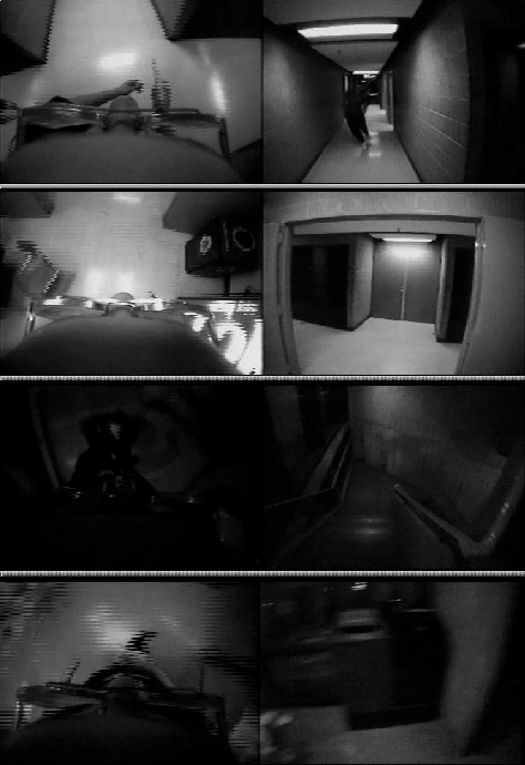 |
Hidden Markov models were chosen to represent the environment due to their potential language structure and excellent discrimination ability for varying time domain processes. For example, rooms may have distinct regions or lighting through which the player passes. Such regions can be modeled by the states in an HMM. In addition, the previous known location of the user helps to limit his current possible location. By observing the video stream over several minutes and knowing the physical layout of the building, many possible paths may be hypothesized and the most probable chosen based on the observed data. Prior knowledge about the mean time spent in each area may also be used to weight the probability of a given hypothesis. HMM's fully exploit these attributes.
The ColorSample module is used to construct a feature vector from three video patches chosen from the two camera images. One patch is taken from approximately the center of the image of the forward-looking camera. The averages of the red, green, blue, and luminance pixel values are determined, creating a four element vector. This patch varies significantly due to the continuous head motion of the player. The next patch is derived from the downward-looking camera in the area just to the front of the player and out of range of average hand and foot motion. This patch represents the color of the floors. Finally, a patch is sampled from the nose, since it is always in the same place relative to the downward-looking camera. This patch provides a hint at lighting variations as the player moves through a room. Combined, these patches provide a 12 element feature vector.
Approximately 45 minutes of Patrol video were analyzed for this experiment. Processing occurs at 10 frames per second on an SGI O2. Missed frames are filled by simply repeating the last feature vector at that point. The data stream is then subsampled to six frames per second to create a manageable database size for HMM analysis. The video is hand annotated to provide the training database and a reference transcription for the test database. Whenever the player steps into a new area, the video frame number and area name are recorded. Both the data and the transcription are converted to Entropic's HTK [252] format using HTKPrepare for training and testing.
For this experiment, 24.5 minutes of video, including 87 area transitions, are used for training the HMM's. As part of the training, a statistical (bigram) grammar is generated. This ``grammar'' is used in testing to weight those rooms which are considered most probable based on the current hypothesized room. An independent 19.3 minutes of video, including 55 area transitions, are used for testing. Note that the computer must segment the video at the area transitions as well as label the areas properly.
Table 6.1 demonstrates the accuracies of the different methods tested. For informative purposes, accuracy rates are reported both for testing on the training data and the independent test set. The simplest method for classifying the current room, the nearest neighbor method, determines the smallest Euclidean distance between a test feature vector with the means of the feature vectors comprising the different room examples in the training set. In actuality, the mean of 200 video frames surrounding a given point in time is compared to the room classifications. Since the average time spent within an area is approximately 600 video frames (or 20 seconds), this window should smooth the data such that the resulting classification shouldn't change due to small variations in a given frame. However, many insertions still occur, causing the large negative accuracies shown in Table 6.1.
Given the nearest neighbor method as a comparison, it is easy to see how the time duration and contextual properties of the HMM's improve recognition. Table 6.1 shows that the accuracy of the HMM system, when tested on the training data, tends to improve as more states are used in the HMM. This results from the HMM's overfitting the training data, as expected. Testing on the independent test set shows that the best model is a 3-state HMM, which achieves 82% accuracy. The topology for this HMM is shown in Figure 6-5. In some cases accuracy on the test data is better than the training data. This effect may be due to weakening batteries causing more variation in the section of video used for the training data.
Accuracy is but one way of evaluating this method. Another important attribute is how well the system determines when the player has entered a new area. Figure 6-6 compares the 3-state HMM and nearest neighbor methods to the hand-labeled video. Different rooms are designated by two letter identifiers, as shown in Figure 6-1, for convenience. As can be seen, the 3-state HMM system tends to be within a few seconds of the correct transition boundaries while the nearest neighbor system oscillates between many hypotheses. In fact, careful examination of the hand labeled reference data shows that the labeling is often in error by a few seconds. Changing the size of the averaging window might improve accuracy for the nearest neighbor system. However, the constantly changing pace of the Patrol player necessitates a dynamically changing window. This constraint would significantly complicate the method. In addition, a larger window would result in less distinct transition boundaries between areas.
As mentioned earlier, one of the strengths of the HMM system is that it can collect evidence over time to hypothesize the player's path through several areas. How much difference does this incorporation of context make on recognition? To determine this, the test set was segmented by hand, and each area was presented in isolation to the 3-state HMM system. At face value this should be a much easier task since the system does not have to segment the areas as well as recognize them. However, the system only achieved 49% accuracy on the test data and 78% accuracy on the training data. This result provides striking evidence of the importance of using context in this task and hints at the importance of context in other user activities.
While the current accuracy rate of the location system is good, several significant improvements can be made. Optical flow or inertial sensors could limit frame processing to those times when the player is moving forward. This would eliminate much of the variation, often caused by stand-offs and firefights, between examples of moving through a room. Similarly, the current system could be combined with optical flow to compensate for drift in inertial trackers and pedometers. Windowing the test data to the size of a few average rooms could improve HMM accuracies as well. Additionally, color histograms could be used as feature vectors instead of the average color of the video patches.
The grammar generated above might also be used for predicting movement through the playing field. For example, the computer can weight the importance of incoming information depending on where it believes the player will move next. An encounter among teammates several rooms away may be relevant only if the player is moving rapidly in that direction. In addition, if the player is shot, the computer may predict the most likely next area for the enemy to visit and alert the player's team as appropriate. Another interesting extension would be to combine all of these techniques in an attempt to create a dynamically updated map of a new building as a military or police force explores it. Such just-in-time information may prove invaluable in some situations.
For the purposes of DUCK!, player actions of interest include aiming, shooting, and reloading. Other actions such as standing, walking, running, and scanning the environment may be executed simultaneously with these actions. In cooperation with Bernt Schiele [217], Schiele and Crowley's generic object recognition system, based on multidimensional receptive field histograms, was adopted to recognize the three player actions of interest [190]. The goal is to differentiate between three classes: reloading, aiming and shooting, and ``other.'' Figure 6-7 shows examples of images of each of these actions.
Two minutes of video were hand annotated for these classes. During this time, thirteen aiming/shooting, six reloading, and ten ``other'' occurences were observed. These events were separated into a training set of seven aiming, four reloading, and three other occurences with the remainder designated as a test set. Thirty images corresponding to the same action were chosen arbitrarily from the training data and were split into sixteen sub-images taken from a four by four grid. These sub-images were taken from positions in the image where the player's hands might appear. Each group of thirty defined the training set for the Schiele subsystem. Next, for each frame analyzed, the Schiele subsystem output 48 probabilities: the probability that each of the image patches in the 4 by 4 grid of the incoming video matches each of the three classes of actions. A 5-state left-right HMM was defined for each class, and the time sequence of feature vectors from the training set was used to train each model. Finally, the test sequences were played individually and the system returned the most probable classes. Table 6.2 shows the confusion matrix of the three action classes.
|
While realizing this system would require transcribing and analyzing more video than is currently possible, the results from this initial inquiry are encouraging. Actions presented in isolation are recognized with an accuracy of 86%. Even though the quality of the video is poor, the resolution low, the lighting variable, and the task extremely rugged and demanding, it seems that useful information can be recovered during game play. In particular, the 100% recognition of aiming gestures with no confusion could be extremely useful. Of course, other methods may be used to help classify the player's actions. For example, the gun itself can be instrumented with sensors indicating its orientation and whether or not it is loaded. However, such methods would be specific to this application and not generalize to everyday living.
DUCK! is intended as an initial exploration of how context might be recovered and used in non-laboratory conditions. The experiments above suggest that the perception and modeling techniques are promising; however, how do we know such a system would be useful? The most straightforward way to answer this question is to implement the system and run a series of trials. A fixed set of teams would be defined, and one team would be chosen for testing. Over a series of games, the test team would play both with and without the wearable computer aids. Success would be measured by an increased number of kills, a higher ratio of kills versus casualties, and a decreased number of ``friendly fire'' casualties. Since players often maintain these performance statistics during a game as a matter of pride, these values seem a good evaluation metric. Unfortunately, a suitable wearable computer would require two networked SGI O2's, a wireless network, and the batteries for an appropriate run time in addition to the current equipment in the video backpack. Even with modifying the O2's for embedded use, the resulting backpack would weigh approximately 70 pounds and cost at least $50,000 to manufacture. Not only are three such devices prohibitively expensive and time-consuming to make, but the equipment would significantly impair the players who used them.
A second method of evaluation is to simulate the information the perceptual system provides and create a suitable apparatus to display the information for the players. One way to do this is to use wireless video transmitters in conjunction with the video backpack. Besides requiring a complicated infrastructure to support many channels of video and the numerous machines for real-time processing, the video backpack itself weighs enough to impair players. In fact, it may be very difficult to find subjects who would use this equipment. Thus, this method is untenable as well.
Instead of using on-body cameras, cameras could be mounted in the environment to observe every area of the Patrol playing field. Human observers would track each player on the test team noting location and actions in real-time. This data would be compiled by a central computer which would render the appropriate BattleMaps for each player, and the BattleMaps would be sent to each player's display. Current wearable computers are sufficient for this display task and can be made small and light enough not to hinder the player significantly. While this method ignores one of the main thrust of this project, using perception and modeling to avoid off-body infrastructure, it is feasible with enough money and personnel.
From a rough survey of the environment, a minimum of 50 cameras would be needed to cover the Patrol field. The resulting video would sent to an observer room. Each player on the test team would be assigned a human observer. Each observer would use a pressure sensitive tablet with a map overlay of the Patrol field to indicate the current position of his player. In addition, the observer would indicate his player's actions, chosen from a preselected set, through a simple keyboard. Assuming that the human observers can perform satisfactorily for the perceptual task, human factors studies can be run with different interfaces and styles of maps in addition to an evaluation of the effectiveness measures mentioned above. While such an experiment is designed to be run in real-time, many questions can be asked if the data is also recorded. Did the human observers perform well? How does this compare to the perceptions of the observers themselves? How did the observers judge the player's actions when the player's back was to the camera? Could a computer vision system be created that performs as well using the room-based cameras? What other information could be recovered that might be useful to the Patrol player? How should this information be presented? A detailed examination of the resulting video tapes would reveal much about Patrol game play, player communication, foot traffic patterns, and system effectiveness. Unfortunately, the cost in hardware and personnel put such an experiment beyond the scope of this project. However, in an initial exploration such as this in which mock-ups of the interface have been developed, much can be learned from a discussion with a domain expert [141].
Desiring feedback on the potential future use of the DUCK! system, I elicited the help of another expert Patrol player. While the expert had seen the apparatus during game play, he did not know the details of the experiment. To begin, I explained what information the apparatus could recover and how this information would be shared between players. In addition, I demonstrated the types of displays that might be used in a player's cap and explained that the expert should think in terms of future hardware, in which the cameras, processing, and wireless networking disappear into the player's clothing.
In order to talk concretely about the BattleMap concept and its potential uses, I created a demonstration using data from the above perception experiments. The transcription of the locations and actions of the DUCK! subject was split into three segments. These three segments were then composited to create the appearance of a team of three players. The TimedData module was used to create a ``real-time'' stream of data for the BattleMap prototypes to display. Since each segment of data was of a different length and was designed to loop realistically, the composited data gave an appearance of a continually evolving game.
To enable discussion, the BattleMap prototypes were displayed on a monitor on which both the expert and the author could refer to them. The intention was to get the expert thinking aloud about the display and its potential uses. After a brief explanation, both styles of interface as shown in Figures 6-2 and 6-3 were shown to the expert. When asked which he would prefer, the expert indicated the display with arrows for the reason that, even though the predicted direction may be incorrect, the arrows provided additional tactical information that could be obtained with a glance at the display. This opinion matched the author's own preferences.
Working from this second, preferred set of graphics, more specific questions were asked. Should the arrows be bigger? Is the flashing (indicating a firefight) too distracting? In response, the expert indicated that these features seemed fine, but he would prefer if he could distinguish each player, since perceived experience levels of teammates can significantly impact the behavior of the player. Next, the expert was instructed to evaluate different audio interfaces. The interface could beep at the beginning and end of aiming and reloading gestures, at just the beginning of each gesture, at the beginning of just aiming gestures, or upon the first instance of a gesture that might indicate a firefight. I showed the expert example videotape from which the example interface data was derived. At this point the expert began to ask detailed questions about the sensing capabilities of the hardware. Can it really distinguish between aiming and reloading? Does it know the difference between the beginning and end of the gesture? In general the expert thought that the more information that could be conveyed, the better. However, his line of questioning soon led to a more general discussion on the usefulness and suitability of the interface, which was the intent of the interview.
While watching the composited data used to display the capabilities of the interface, both the expert and I began to create viable hypotheses to explain the ``team play'' we were seeing on the screen. Even though I had explicitly explained the composited nature of the data, both of us were compelled to analyze the displayed motion and actions of the ``players'' tactically. Statements such as ``the player recognizes his teammate is in trouble and sees that reinforcements are coming from the back hall, so he is sneaking up the mezzanine stairs to trap the enemy and shoot him in the back'' were common in the discussion. As we watched the playback of the data, the expert suggested more and more situations in which the interface could make a significant difference. These situations were eventually classified into ``far'' and ``near'' effects.
``Far'' effects are when a player is not directly involved with a teammate but is instead trying to determine his next best course of action in helping the team. These situations were expected in the design of the system, as outlined previously. For such situations the expert agreed that the most salient information was the location of teammates and whether or not they were aiming at someone, indicating an active firefight or a standoff. In general, a player will choose to join his nearest teammate unless another teammate is actively engaging an enemy. In such a case, the player will try to move the enemy from his current secure position by coming from an unexpected direction to help his teammate. An interesting point raised in the discussion is that this rule of thumb is conditioned by the likelihood of the player encountering resistance along the way. For example, the ``T junction'' presents a significant barrier to travel due to its highly exposed nature. Thus, teammates on the opposite side of the T junction are generally ignored unless the T junction is uncontested and held by the player's team. The expert and I agreed that the volume of the aiming tones should be scaled to indicate the travel effort predicted to be needed to reach an embattled teammate versus the actual Euclidean distance.
What was not expected were the perceived advantages of the interface when working closely with another team member. As stated earlier, a player returning to the active playing field may decide to help a currently engaged teammate. However, the teammate may not realize that the returning player is on the same team and will accidentally shoot him. Typically this happens because the teammate has fired his single shot and is temporarily running from the current engagement while he is reloading. Since reloading is almost completely a ``by touch'' process for the Patrol player, he can afford a glance at his display while reloading and may discover that the right tactic is to lead a chasing adversary to his returning teammate. From the point of view of the returning player, the pattern of aiming/shooting and reloading indicate not only the skill of the teammate but the amount of trouble he is having. In the situation above, an aiming gesture followed by movement and a reload indicates that a teammate is being chased and the player should prepare to ambush the chaser. In order to help distinguish these actions in such a situation, the expert suggested that separate audio signals should be used to indicate aiming and reloading. As a related item, the expert asked if the DUCK! system could be used to render teammates' positions as if the player could ``see-through'' walls. I explained that recovery of head motion would be necessary for that function and that the results would not be precise. However, I also asked when such a function would be useful. The expert indicated that while the overlay may be distracting in general, it would be useful for close team work as the situation above.
Another typical situation described by the expert and ``seen'' on the example interface is when two teammates are holding a room from opposite doorways. In such a situation, in which the players are essentially isolated from the rest of the game and actively engaged with another team, the graphical display is not very useful. Instead, audio cues should be used. In this situation, when Player A fires, he is vulnerable and so is his teammate, Player B, if he does not pay attention to long distance attacks. The proper behavior for Player B is to take a step back from his door and divide his attention between both doors until the Player A reloads. If the opposing team charges through Player A's door, Player B runs to cover Player A's door, giving Player A time to reload and cover Player B's original door. In reality, the defending team will encourage a charge by the opposing team so as to take out first one threat and then the other. The most dangerous situation is when both doorways are threatened with a synchronized or slightly staggered attack. In this situation, both defenders must try to hold their ground, firing only when necessary and hopefully never at the same time leaving them defenseless. A defender may aim his gun at an adversary simply as a holding action with little intent to fire. The rhythm of aimings, firings, and reloads can help teammates determine the level of danger for a particular defender. In addition, if a defender has spent his dart and is in the process of dodging a charging player's darts, he will change his dodging pattern to keep an open line of fire if he thinks his teammate has a reloaded weapon. However, while the firing of a Patrol gun has a distinctive sound, aiming is silent, and reloading is difficult to hear. In addition, a player does not want to announce publicly that he has run out of darts. Thus, the expert suggested that a system which could unobtrusively ``announce'' a teammate's actions from across an area would significantly enhance defensive team play.
Another surprising observation made by the user is that, since the system can recognize real gestures made in the course of play, it could also recognize gestures whose express purpose was to communicate silently with other team members. In this manner, players can communicate strategy when stealth is necessary. A simple example is that a player who spies a group of adversaries could make several rapid aim gestures alerting his teammates to the number of opposing players without necessarily revealing the scout's location. With the adoption of more complicated, explicit gestures such as found in the ASL project, information such as deployment and ammunition reserves could be communicated.
One of the final opinions elicited from the expert was what effect errors from the perceptual system might have on the use of the system. Since location discrepancies mostly involved nearby areas, the expert felt that these errors were acceptable for players planning their return to the game. Similarly, since the aiming gesture is the most crucial in determining when a teammate is in need of help, the gesture recognition system was thought appropriate for the strategy planning task. After considering the accuracies of the components of the system above and the types of likely errors, the expert thought that the DUCK! interface would be of significant strategic importance during game play and would probably change the way the game is played.
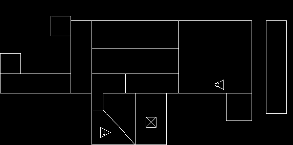 |
Using the information gained from this interview, the interface was redesigned as shown in Figure 6-8 to reflect the identity of the players. However, with a small number of team members, color might be used to help differentiate the players at a glance [148]. Distinctive tones were added for aiming and the ending of reloading as suggested to help with close team work.
Of course, the opinions expressed by two expert players on a prototype interface only begin to address the issues that would be raised by a full implementation of the DUCK! system. However, the basic observations above are echoed in electronic map studies from other fields. Maps have long been used for navigation and situation awareness [184]. With the advent of electronic displays, maps have become dynamic and interactive. A map can be rotated to correspond to the user's current direction of travel or even rendered in three dimensions overlaying the virtual features of the map on the user's physical view [184]. In aviation, it has been found that such techniques can reduce errors and stress for local navigation but limit planning over larger areas [246,245]. When planning strategy over a larger area, a fixed orientation map is more appropriate [136]. Thus, given the detailed knowledge of Patrol players of the playing field and the intended use during resurrection, the fixed position DUCK! BattleMap seems appropriate for player strategy planning. However, close team collaboration using the DUCK! apparatus might use overlays as suggested by the expert. Given the unique constraints of Patrol, only a test implementation can fully explore such close combat situations.
DUCK! suggests how a wearable computer system may assist a player using only information sensed from the user's normal actions during his primary task. The player need not direct the computer explicitly nor modify his behavior for the computer's benefit. In addition, DUCK! hints that off-body infrastructure may not be necessary in recovering user location or natural gesture.
The DUCK! system provides many opportunities for future exploration. As stated previously, more sophisticated features and other sensing modalities may be explored to improve precision and accuracy. Larger databases of video, taken from several Patrol games, may be used to create a more robust system. As hardware continues to become smaller and require less power, a full, real-time implementation may be tested. Most importantly, the concepts explored in DUCK! can be tested in more common situations, such as office, construction, power production, or medical environments. Future applications may include training, safety, remote collaboration, or personalized information assistants.
The three preceding chapters have demonstrated projects that dedicate progressively larger portions of their sensing and modeling effort for context awareness. Hopefully, such contextually aware systems will lead to more graceful interfaces where the user may spend less attention on the computer and more attention to his primary task while still receiving timely information support. However, the sensors and processing necessary for such systems quickly lead to physical limitations on these systems, especially pronounced in this chapter. The next three chapters of this thesis will examine some of the physical limitations of current wearable computing technology and suggest some novel methods to improve such devices.
While computational hardware has reduced in size quickly, power systems are still bulky and inconvenient. Today's laptops and PDA's are often limited in functionality by battery capacity, output current, and the necessity of having an electrical outlet within easy access for recharging. With wearable computers, the problem would seem to worsen. As part of the definition provided earlier, wearables are constantly monitoring their users' environment. Such sensing often requires power hungry peripherals, and a wearable computer's form factor sets a limit to its power reserves. Additionally, wearables computers are designed to be used all day, hopefully without subjecting the user to switching batteries every hour. These constraints make a compromise between form and functionality difficult. However, if energy can be harnessed from the user's casual activities and actions, these problems will be alleviated. This chapter, an earlier version of which was published in the IBM Systems Journal in 1996 [207], explores this concept.
First, a review of vocabulary and units is in order.
Energy is defined as the capacity to do work. For this thesis, the
joule will be used as the standard unit of energy. A joule
(
 ) is the product of a force of one newton acting
through a distance of one meter. For reference, Table
7.1 compares some common sources of energy.
The calorie, which is
) is the product of a force of one newton acting
through a distance of one meter. For reference, Table
7.1 compares some common sources of energy.
The calorie, which is  joules, is also often used as a unit of
energy. However, in dietary circles, a Calorie refers to a
kilocalorie or
joules, is also often used as a unit of
energy. However, in dietary circles, a Calorie refers to a
kilocalorie or  calories. Therefore, an average adult diet of
2,500 Calories translates to
calories. Therefore, an average adult diet of
2,500 Calories translates to  .
.
| Energy sources | Computing power requirements | |
AA alkaline battery:  |
desktop (without monitor):  |
|
camcorder battery:  |
notebook:  |
|
liter of gasoline:  |
embedded CPU board:  |
|
calorie:  |
low power microcontroller chip:  |
|
(dietary) Calorie:  |
average human power use over 24 hours:  |
|
average human diet:
 |
Power, often confused with energy, is the time rate of doing
work. Power can be measured in watts (
 ),
or joules per second. Table 7.1 also shows power
requirements for common computing devices. The reader should be aware
that in some literature, units of power are combined with units of
time to indicate energy. For example, watt seconds, watt hours, and
kilowatt hours are often used in favor of joule, kilojoule, and
megajoule.
),
or joules per second. Table 7.1 also shows power
requirements for common computing devices. The reader should be aware
that in some literature, units of power are combined with units of
time to indicate energy. For example, watt seconds, watt hours, and
kilowatt hours are often used in favor of joule, kilojoule, and
megajoule.
As shown by human powered flight efforts [226], the human
body is a tremendous storehouse of energy. For example, the energy
obtained from a jelly doughnut is

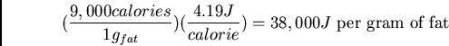

The body also consumes energy at a surprising rate, generally using
between 70,000 and 1,400,000 calories per hour depending on the
activity (see Table
7.2, derived from Morton [143]). In fact, trained athletes can expend close to
9.5 million calories per hour for short bursts [143]. On
the other hand, the energy rate, or power, expended while sleeping is
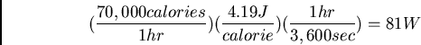
Recent technology makes these tasks easier. Computers are now small enough to disappear into the user's clothing or body. With such small devices, the main power consumers, namely the CPU and storage, can be located near the implemented power source. However, interface devices, such as keyboards, displays, and speakers, have limitations as to their placement on the body. These devices may communicate wirelessly via a ``body network'' as described by Zimmerman [254]. They may generate their own power, share in a power distribution system with the main generator (wired or wireless), or use extremely long lasting batteries. Thus, depending on the user interface desired, wires may not be needed for power or data transfer among the components of a wearable computer.
In the following sections, power generation from breathing, body heat, blood transport, arm motion, typing, and walking are discussed. While some of these ideas are fanciful, each has its own peculiar benefits and may be applied to other domains such as medical systems, general consumer electronics, and user interface sensors. More attention is given to typing and walking since these processes seem more practical sources of power for general wearable computing.
| Activity | Kilocal/hr | Watts | |
| sleeping | 70 | 81 | |
| lying quietly | 80 | 93 | |
| sitting | 100 | 116 | |
| standing at ease | 110 | 128 | |
| conversation | 110 | 128 | |
| eating meal | 110 | 128 | |
| strolling | 140 | 163 | |
| driving car | 140 | 163 | |
| playing violin or piano | 140 | 163 | |
| banging head against wall | 150 | 175 | |
| housekeeping | 150 | 175 | |
| carpentry | 230 | 268 | |
| hiking, 4 mph | 350 | 407 | |
| swimming | 500 | 582 | |
| mountain climbing | 600 | 698 | |
| long distance run | 900 | 1,048 | |
| sprinting | 1,400 | 1,630 |
Since the human body eliminates energy as heat, it
follows naturally to try to harness this energy. However, Carnot
efficiency puts an upper limit on how well this waste heat can be
recovered. Assuming normal body temperature and a relatively low room
temperature ( C), the Carnot efficiency is
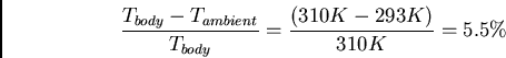
 C) the Carnot efficiency drops to

However, even under the best of conditions (basal, non-sweating), evaporative heat loss accounts for 25% of the total heat dissipation. This ``insensible perspiration'' consists of water diffusing through the skin; sweat glands keeping the skin of the palms and soles pliable; and the expulsion of water-saturated air from the lungs [79]. Thus, the maximum power available, without trying to reclaim heat expended by the latent heat of vaporization, drops to 2.8-4.8 W.
The above efficiencies assume that all of the heat radiated by the body is captured and perfectly transformed into power. However, such a system would encapsulate the user in something similar to a wet suit. The reduced temperature at the location of the heat exchanger would cause the body to restrict blood flow to that area [79]. When the skin surface encounters cold air, a rapid constriction of the blood vessels in the skin allows the skin temperature to approach the temperature of the interface so that heat exchange is reduced. This self-regulation causes the location of the heat pump to become the coolest part of the body, further diminishing the returns of the Carnot engine unless a wet suit is employed as part of the design.
While a full wet suit or even a torso body suit is unsuitable for many applications, the neck offers a good location for a tight seal, access to major centers of blood flow, and easy removal by the user. The neck is approximately 1/15 of the surface area of the ``core'' region (those parts that the body tries to keep warm at all times). As a rough estimate, assuming even heat dissipation over the body, a maximum of 0.20-0.32 W could be recovered conveniently by such a neck brace. The head may also be a convenient heat source for some applications where protective hoods are already in place. The surface area of the head is approximately 3 times that of the neck and could provide 0.60-0.96 W of power given optimal conversion. Even so, the practicality, comfort, and efficacy of such a system are relatively limited.
An average person of 68 kg has an approximate air intake
rate of 30 liters per minute [143]. However, available
breath pressure is only 2% above atmospheric pressure
[250,163]. Increasing the effort required for intake of
breath may have adverse physiological effects [163] so only
exhalation will be considered for generation of energy. Thus, the available power is

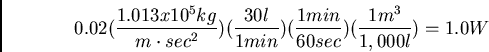
Harnessing the energy from breathing involves breath masks which encumber the user. For some professionals such as military aircraft pilots, astronauts, or handlers of hazardous materials, such masks are already in place. However, the efficiency of a turbine and generator combination is only about 40% [85], and any attempt to tap this energy source would provide additional load on the user. Thus, the benefit of the estimated 0.40 W of recoverable power has to be weighed against the other, more convenient methods discussed in the following sections.
Another way to generate power from breathing is to fasten a tight band
around the chest of the user. From empirical measurements, there is a
2.5 cm change in chest circumference when breathing normally and up to
a 5 cm change when breathing deeply. A large amount of force can be
maintained over this interval. Assuming a respiration rate of 10
breaths per minute and an ambitious 100 N force
applied over the maximal 0.05 m distance, the total power that can
be generated is

While powering electronics with blood pressure may seem impractical,
the numbers are actually quite surprising. Assuming an average blood
pressure of 100 mm of Hg (normal desired blood pressure is 120/80
above atmospheric pressure), a resting heart rate of 60 beats per
minute, and a heart stroke volume of 70 ml passing through the aorta
per beat
[22], then the power generated is

While this energy rate can easily double when running, harnessing this power is difficult. Adding a turbine to the system would increase the load on the heart, perhaps dangerously so. However, even if 2% of this power is harnessed, low power microprocessors and sensors could run. Thus, self-powering medical sensors and prostheses could be created.
Comparison of the activities listed in Table
7.2 indicates that violin playing and housekeeping
use up to 30 kcal/hr, or


A less encumbering system might involve mounted pulley systems in the elbows of a jacket. The take-up reel of the pulley system could be spring-loaded so as to counter-balance the weight of the user's arm. Thus, the system would generate power from the change in potential energy of the arm on the down stroke and not require additional energy by the user on the up stroke. The energy generation system, the CPU, and the interface devices could be incorporated into the jacket. Thus, the user would simply don his jacket to use his computer. However, any pulley or piston generation system would involve many inconvenient moving parts and the addition of significant mass to the user.
A more innovative solution would be to use piezoelectric materials at the joints which would generate charge from the movement of the user. Thus, no moving parts per se would be involved, and the jacket would not be significantly heavier than a normal jacket. However, as will be seen in the next sections, materials with the appropriate flexibility have only 11% efficiency, making the recoverable power 0.33 W.
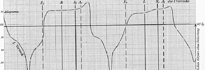 |
Using the legs is one of the most energy consuming activities the
human body performs. In fact, a 68 kg man walking at 3.5 mph, or 2
steps per second, uses 280 kcal/hr or 324 W of power [143].
Comparing this to standing or a strolling rate implies that over half
this power is being used for moving the legs. While walking, the
traveler puts up to 30% more force on the balls of his feet than
that provided by his resting body weight (Figure 7-1,
first published in Braune and Fischer [21]). However, calculating the power
that can be generated by simply using the fall of the heel through 5
cm (the approximate vertical distance that a heel travels in the human
gait [21]) reveals that

Piezoelectric materials create electrical charge when mechanically
stressed. Among the natural materials with this property are quartz,
human skin, and human bone, though the latter two have very low coupling
efficiencies. Table 7.3, composited from a variety of sources [3,70,4], shows properties of
common industrial piezoelectric materials: polyvinylidene fluoride
(PVDF) and lead zirconate titanate (PZT). For convenience, references
for data sheets and several advanced treatments of piezoelectricity
are included [3,26,70,92,179].
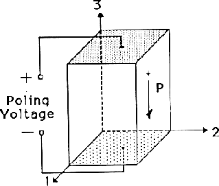 |
The coupling constant shown in Table 7.3 is the efficiency with which a material converts mechanical energy to electrical. The subscripts on some of the constants indicate the direction or mode of the mechanical and electrical interactions (see Figure 7-2 from [4]). "31 mode" indictates that strain is caused to axis 1 by electrical charge applied to axis 3. Conversely, strain on axis 1 will produce an electrical charge along axis 3. Bending elements, made by an expanding upper layer and a contracting bottom layer, are made to exploit this mode in industry. In practice, such bending elements have an effective coupling constant of 75storage of mechanical energy in the mount and shim center layer.
The most efficient energy conversion, as indicated by the coupling
constants in Table 7.3, comes from compressing PZT ( ).
Even so, the amount of effective power that could be
transferred this way is minimal since compression follows the formula
).
Even so, the amount of effective power that could be
transferred this way is minimal since compression follows the formula
 is force,
  is the unloaded height, is the area over
which the force is applied, and
is the unloaded height, is the area over
which the force is applied, and  is the elastic modulus. The
elastic modulus for PZT is
is the elastic modulus. The
elastic modulus for PZT is  N/m
N/m . Thus, it would take an
incredible force to compress the material a small amount. Since energy
is defined as force through distance, the effective energy generated
through human-powered compression of PZT would be vanishingly small,
even with perfect conversion.
. Thus, it would take an
incredible force to compress the material a small amount. Since energy
is defined as force through distance, the effective energy generated
through human-powered compression of PZT would be vanishingly small,
even with perfect conversion.
On the other hand, bending a piece of piezoelectric material
to take advantage of its 31 mode is much easier. Because it is
brittle, PZT does not have much range of motion in this direction.
Maximum surface strain for this material is
 .
Surface strain can be defined as
.
Surface strain can be defined as
 is the deflection, is the thickness of the beam, and
  is the cantilever length. Thus, the maximum deflection or bending for
a beam (20 cm) of a piezoceramic thin sheet (0.002 cm) before failure
is
is the cantilever length. Thus, the maximum deflection or bending for
a beam (20 cm) of a piezoceramic thin sheet (0.002 cm) before failure
is
PVDF, on the other hand, is very flexible. In addition, it is easy to
handle and shape, exhibits good stability over time, and does not
depolarize when subjected to very high alternating fields. The cost,
however, is that PVDF's coupling constant is significantly lower than
PZT's. Also, shaping PVDF can reduce the effective coupling of
mechanical and electrical energies due to edge effects. Furthermore,
the material's efficiency degrades depending on the operating climate
and the number of plies used. Fortunately, from an industry
representative [86], we know a 116 cm 40 ply
triangular plate with a center metal shim deflected 5 cm by 68 kg 3 times every 5 seconds results in the generation of 1.5 W of
power. This result is a perfect starting point for the calculations
in the next section.
Consider using PVDF shoe inserts for recovering some of the power in
the process of walking. There are many advantages to this tactic.
First, a 40 ply pile would be only (28 m)(40) = 1.1 mm thick
(without electrodes). In addition, the natural flexing of the shoe
when walking provides the necessary deflection for generating power
from the piezoelectric pile (see Figure 7-3). PVDF is easy
to cut into an appropriate shape and is very durable
[3,70]. In fact, PVDF might be used as a direct
replacement for normal shoe stiffeners. Thus, the inserts could be easily put
into shoes without moving parts or seriously redesigning the shoe.
A small women's shoe
has a footprint of approximately 116 cm. Knowing that the maximum
effective force applied at the end of a user's step increases the
apparent mass by 30%, the user needs only 52 kg (115 lbs) of mass to
deflect the PVDF plate a full 5 cm. While the
numbers given in the last section were for a 15.2 cm by 15.2 cm
triangular 40 ply pile, the value can be used to approximate the
amount of power an appropriately shaped piezoelectric insert could
produce. Thus, scaling the previous 1.5 W at 0.6 deflections per
second to 2 steps per second,
Through the use of a cam and piston or ratchet and flywheel mechanism, the motion of the heel might be converted to electrical energy through more traditional rotary generators. The efficiency for industrial electrical generators can be very good. However, the added mechanical friction of the stroke to rotary converter reduces this efficiency. A normal car engine, which contains all of these mechanisms and suffers from inefficient fuel combustion, attains 25% efficiency. Thus, for the purposes of this section, 50% conversion efficiency will be assumed for this method, which suggests that, conservatively, 17-34 W might be recovered from a ``mechanical'' generator.
How can this energy be recovered without creating a disagreeable load on the user? A possibility is to improve the energy return efficiency of the shoe and tap some of this recovered energy to generate power. Specifically, a spring system, mounted in the heel, would be compressed as a matter of course in the human gait. The energy stored in this compressed spring can then be returned later in the gait to the user. Normally this energy is lost to friction, noise, vibration, and the inelasticity of the runner's muscles and tendons (humans, unlike kangaroos, become less efficient the faster they run [143]). Spring systems have approximately 95% energy return efficiency while typical running shoes range from 40% to 60% efficiency [90]. Volumetric oxygen studies have shown a 2-3% improvement in running economy using such spring systems over typical running shoes [90]. Similarly suggestive are the "tuned" running track experiments of McMahon [139]. The stiffness of the surface of the indoor track was adjusted to decrease foot contact time and increase step length. The result was a 2-3% decrease in running times and seven new world records in the first two seasons of the track. Additionally, a reduction in injuries and increase of comfort was observed. Thus, if a similar spring mechanism could be designed for the gait of normal walking, and a ratchet and flywheel system is coupled to the up stroke of the spring, it may be possible to generate energy while still giving the user an improved sense of comfort (Figure 7-3). In fact, active control of the loading of the generation system may be used to adapt energy recovery based on the type of gait at any given time.
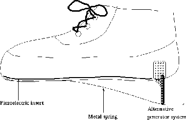 |
Since a simple mechanical spring would not provide constant force over the fall of the heel but rather a linear increase (for the ideal spring), only about half of the calculated energy would be stored on the down step. An open question is what fraction of the spring's return energy can be sapped on the upstep while still providing the user with the sense of an improved ``spring in the step'' gait. Initial mock-ups have not addressed this issue directly, but a modern running shoe returns approximately 50% of the 10J it receives during each compression cycle (such ``air cushion'' designs were considered a revolutionary step forward over the hard leather standard several decades ago). Given a similar energy return over the longer compression distance of the spring system, the energy storage of the spring, and the conversion efficiency of the generator, 12.5% of the initial 67 W is harnessed for a total of 8.4 W of available power.
A final potential method of generating power is to harness air
drag while the user is walking. At a 6 mph run, only 3% of the
expended energy ( ) is performed against air resistance [143].
While 30 W of power is a significant amount, little of this energy
could be harnessed without severely encumbering the user. At more
reasonable walking speeds, the available power declines sharply.
Thus, it seems pointless to pursue a hard-to-recover energy source
which can only yield 3% of the user's total energy when leg motion
may consume over 50% of the total energy during the same activity.
) is performed against air resistance [143].
While 30 W of power is a significant amount, little of this energy
could be harnessed without severely encumbering the user. At more
reasonable walking speeds, the available power declines sharply.
Thus, it seems pointless to pursue a hard-to-recover energy source
which can only yield 3% of the user's total energy when leg motion
may consume over 50% of the total energy during the same activity.
Keyboards will continue to be a major interface for computers into the
next decade [214]. As such, typing may provide a useful
source of energy. On a one-handed chording keyboard (HandyKey's
Twiddler), it is necessary to apply 130 grams of pressure in order to
depress a key the required 1 mm for it to register. Thus,

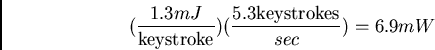

Current notebook computers offer a unique method for generating
energy. Simply opening the computer may supply power. However, this
one action needs to provide power for the entire session; otherwise,
users would be forced to flap their computers open and closed. From
some simple empirical tests, the maximum force that a user may
reasonably expect to exert when opening a notebook computer is

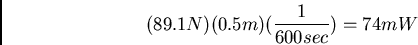
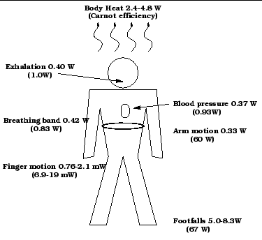 |
Figure 7-4 shows a summary of the body-centered generation methods discussed so far. Every power generation system proposed, with the possible exception of heat conversion, would require some power storage device for periods between power generation cycles. Thus, some attention is necessary regarding the efficiency of storage.
Electrical storage may be preferable due to its prevalence and miniaturization. First however, the power must be converted to a usable form. For the piezoelectric method, a step down transformer and regulator would be needed. Current strategies for converting the high voltages generated by piezoelectric materials to computer voltage levels can attain over 90% efficiency [91]. Care is needed to match the high impedance of the piezo generator properly, and, due to the low currents involved, the actual efficiency may be lower. For the other generation methods, power regulators would be needed as well, and aggressive strategies can attain 93% efficiency.
The most direct solution to the problem of electrical storage is to
charge capacitors that can be drained for power during periods of no
generation. However, simply charging the capacitor
results in the loss of half the available power [75].
Unfortunately, a purely capacitive solution to the problem is also
restricted by size. Current small (less than 16 cm) 5 V
supercapacitors are rated for approximately 3 Farads. Thus, only

 of volume). Note that the zinc-air battery would
mass around 0.12 kg if it could be manufactured in this form factor.
of volume). Note that the zinc-air battery would
mass around 0.12 kg if it could be manufactured in this form factor.
| Property | Lead gel | Nickel cadmium | Nickel metal hydride | Lithium-ion | Zinc-Air | |
| MJ/kg | 0.115 | 0.134 | 0.171 | 0.292 | 0.490 | |
| J/cm |
426 | 354 | 498 | 406 | 571 | |
| on-time (hr) | 2.37 | 1.97 | 2.77 | 2.26 | 3.17 |
Mechanical energy storage may be more attractive for some of the generation mechanisms described above. For example, with walking, flywheels, pneumatic pumps, and clock springs may prove more fruitful in storing power. However, the possibilities are numerous and coverage of the field is beyond the scope of this chapter.
A recent trend in computing is for more capability to be packed into smaller spaces with less power consumption. At first this trend was pushed by laptop computers. With the advent of pen computing and PDA's, components have become even smaller and more manageable. Now it is possible to make a computer which can be worn and run constantly [214].
For example, the author's wearable computer requires an
average of 5 W of power to run all components continuously (head
mounted display, 2G hard disk, 133 MHz 80586 CPU, 20M RAM,
serial/parallel ports, etc.) A standard off-the-shelf 1 kg lead acid
gel cell battery can provide this unit power for 6 hours. However,
such a battery has a volume of 450 cm. Of course, lithium ion
battery technology is now available, which significantly reduces the
weight of the battery. In addition the author's computer does not use
power management currently.
For comparison, a viable wearable computer could be made with the StrongArm microprocessor which requires .3W of power at 115 MIPS. With flash memory instead of rotary disk storage, some driver circuitry, and a Private Eye head mounted display from Reflection Technology Inc., a functional wearable computer (without communications) could be made with a power consumption of 0.7 W. Thus, significant computing power can be obtained even on a relatively strict power budget.
While computing, display, communications, and storage technology may become efficient enough to require unobtrusive power supplies, the desire for the fastest CPU speeds and highest bandwidth possible will offset the trend. In addition, dependence on power cells requires the user to ``plug in'' occasionally. This is impossible in some military and professional contexts. If body motion is used, it may be significantly more convenient to shift weight from one foot to another, for example, than to search for an electrical outlet.
Each of the generation methods has its own strengths and weaknesses depending on the application. However, power generation through walking seems best suited for general purpose computing. Since the original publication of this chapter, evaluations of several prototypes have been published [113,234] and a couple of old studies have been discovered [138,132]. In particular, at the 1998 International Symposium on Wearable Computers, Kymissis et al. [113] demonstrate a mechanical shoe generator that can power a portable radio (250mW) as well as a PZT and a PVDF generator that can power digital RFID transmitters (2mW). The authors compare the convenience and mechanical wear factors of these designs and discuss methods of improving efficiencies. Additionally, McLeish and Marsh, in their 1971 paper, report a user study on a hydraulic shoe pump system used for powering a bionic arm. This system had a relatively small, .375 inch throw which the user reported did not hinder his normal walking. However, this system recovers, on average, 5W of power while the user was walking. While this system suffered from the inconvenience of a hydraulic line running from the pants leg to the arm mounted accumulator, it demonstrates the power ranges predicted in this chapter.
Demand for higher computational power in mobile devices has forced hardware designers to plan processor heat dissipation carefully. However, as owners of high-end laptops will testify, the surface of the machine may still reach uncomfortable temperatures, especially upon momentary contact. Wearable computers would seem to have particular difficulties since the computer housing may be in prolonged contact with skin. However, this chapter suggests that wearable computers may provide a better form factor than today's notebooks in regard to heat dissipation.
An obvious approach to the problem of heat generation is to decrease
the power required for high-end CPUs through higher integration,
optimized instruction sets, and more exotic techniques such as
``reversible computation'' [253]. However, profit margins,
user demand, and backwards compatibility concerns are pushing industry
leaders to concentrate on systems requiring more than 5W. In
addition, the peripherals expected on a wearable computer, such as
wireless Internet radios, video cameras, sound cards, body networks,
scanners, and global positioning system (GPS) units, create an ever
higher heat load as functionality increases. An example of this
effect is the U.S. Army's modern (late 1990's) soldier, who is
expected to dissipate up to  on communications gear alone! Thus, even
with improved technology, heat dissipation will continue to be an
issue in the development of mobile devices.
on communications gear alone! Thus, even
with improved technology, heat dissipation will continue to be an
issue in the development of mobile devices.
Currently consumer electronics try to insulate the user from heat
sources, slowing or shutting down when internal temperatures get too
high. However, the human body is one of the most effective and
complex examples of thermoregulation in nature, capable of dissipating
well over  of heat [36]. Thus, the human body itself
might be used to help dissipate heat. To take advantage of this
system, some background knowledge is necessary. The next section
discusses the fundamentals of human heat regulation and thermal
comfort, but for a more general discussion see Clark and Edholm's book
Man and His Thermal Environment [36]. Those readers
who are familiar with the principles of thermoregulation should skip
to the next section.
of heat [36]. Thus, the human body itself
might be used to help dissipate heat. To take advantage of this
system, some background knowledge is necessary. The next section
discusses the fundamentals of human heat regulation and thermal
comfort, but for a more general discussion see Clark and Edholm's book
Man and His Thermal Environment [36]. Those readers
who are familiar with the principles of thermoregulation should skip
to the next section.
In the extremes, the human body generates between  to
to  of
power [143,207]. With proper preparation, it can
survive in the hot Saharan desert or on the ice in Antarctica for
extended periods. Yet, the body maintains its ``core'' temperature
(the upper trunk and head regions) at
of
power [143,207]. With proper preparation, it can
survive in the hot Saharan desert or on the ice in Antarctica for
extended periods. Yet, the body maintains its ``core'' temperature
(the upper trunk and head regions) at  , only varying +/-
  while under stress (in medical extremes, +/-
  may be observed)
[36].
Obviously, the human body can be an excellent regulator of
heat. However, the sedate body is comfortable in a
relatively narrow range of environmental temperatures. Even so, the
amount of heat that is exchanged in this comfort range can be
significant when all the different modes are considered. Heat
balance in the human body can be expressed by
may be observed)
[36].
Obviously, the human body can be an excellent regulator of
heat. However, the sedate body is comfortable in a
relatively narrow range of environmental temperatures. Even so, the
amount of heat that is exchanged in this comfort range can be
significant when all the different modes are considered. Heat
balance in the human body can be expressed by
 is the rate of heat production (due to metabolism),
  is
rate of useful mechanical work,
is
rate of useful mechanical work,
 is rate of heat loss
due to evaporation,
is rate of heat loss
due to evaporation,
 is the rate of heat gained or
lost (exchanged) due to convection,
is the rate of heat gained or
lost (exchanged) due to convection,
 is the rate of
heat exchanged by radiation,
is the rate of
heat exchanged by radiation,
 is the rate of heat
exchanged by conduction, and
is the rate of heat
exchanged by conduction, and
 is the rate of heat storage
in the body. Thus, total body heat may increase or decrease
resulting in changes in body temperature [36].
is the rate of heat storage
in the body. Thus, total body heat may increase or decrease
resulting in changes in body temperature [36].
Body heat exchange is very dependent on the thermal environment. The
thermal environment is characterized by ambient temperature ( ),
dew point temperature () and ambient vapor pressure (
),
dew point temperature () and ambient vapor pressure (
 ), air or fluid velocity (
 ), mean radiant
temperature () and effective radiant field(
), mean radiant
temperature () and effective radiant field( ),
clothing insulation (clo), barometric pressure (
), and exposure time. Ambient temperature is simply the
temperature of the environment outside of the influence of the body.
The dew point temperature is the temperature at which condensation
first occurs when an air-water vapor mixture is cooled at a constant
pressure. Ambient vapor pressure is also a measure of humidity and,
for most cases, is the pressure exerted by the water vapor in the air.
Air and fluid movement are the result of free buoyant motion caused by
a warm body in cool air, forced ventilation of the environment, or
body movement. Mean radiant temperature and the effective radiant
field describe radiant heat exchange. Mean radiant temperature (MRT)
is the temperature of an imaginary isothermal ``black'' enclosure in
which humans would exchange the same amount of heat by radiation as in
the actual nonuniform environment. Effective radiant field (ERF)
relates the MRT or the surrounding surface temperatures of an
enclosure to the air temperature. The ``clo'' is a unit of clothing
insulation which represents the effective insulation provided by a
normal business suit when worn by a resting person in a comfortable
indoor environment. It is equivalent to a thermal resistance of
),
clothing insulation (clo), barometric pressure (
), and exposure time. Ambient temperature is simply the
temperature of the environment outside of the influence of the body.
The dew point temperature is the temperature at which condensation
first occurs when an air-water vapor mixture is cooled at a constant
pressure. Ambient vapor pressure is also a measure of humidity and,
for most cases, is the pressure exerted by the water vapor in the air.
Air and fluid movement are the result of free buoyant motion caused by
a warm body in cool air, forced ventilation of the environment, or
body movement. Mean radiant temperature and the effective radiant
field describe radiant heat exchange. Mean radiant temperature (MRT)
is the temperature of an imaginary isothermal ``black'' enclosure in
which humans would exchange the same amount of heat by radiation as in
the actual nonuniform environment. Effective radiant field (ERF)
relates the MRT or the surrounding surface temperatures of an
enclosure to the air temperature. The ``clo'' is a unit of clothing
insulation which represents the effective insulation provided by a
normal business suit when worn by a resting person in a comfortable
indoor environment. It is equivalent to a thermal resistance of
 or a conductance of
 . Barometric pressure is caused by the atmosphere and
usually expressed in kPa (
. Barometric pressure is caused by the atmosphere and
usually expressed in kPa (
 ) or torr.
While the following sections will address these variables where
appropriate, the reader is encouraged to read Gagge and Gonzalez
[73] and Clark [36] for a more extensive treatment.
) or torr.
While the following sections will address these variables where
appropriate, the reader is encouraged to read Gagge and Gonzalez
[73] and Clark [36] for a more extensive treatment.
For most discussions, the outer skin is considered the heat exchange
boundary between the body and the thermal environment. Heat exchange
terms reflect this, having units of . A good
approximation of an individual's skin surface area is given by the
Dubois formula
 |
(2) |
 is the surface area in square meters,
  is body mass in
kilograms, and is height in meters [73]. For
convenience, we assume a user with a skin surface area of
is body mass in
kilograms, and is height in meters [73]. For
convenience, we assume a user with a skin surface area of  and
a mass of
and
a mass of  .
.
In an environment where air temperature is cooler than that of the skin or clothing surface, the air immediately next to the body surface becomes heated by direct conduction. As the air heats, it becomes less dense and begins to rise. This occurs everywhere about the body and forms a micro-environment where heat is transferred by convection (see Figure 8-1. This air flow is called the natural convection boundary layer and can be recorded through Schlieren photography [36].
The amount and velocity of the air created by natural convection can
be surprising. For a standing naked man with mean skin temperature of
 and ambient temperature of
  air velocity reaches
 , and the quantity of air passing over the head is
 . Along the lower meter of the body the air flow
remains laminar, maintaining a warm air barrier against the skin.
Above a transitional zone, turbulent flow develops at
. Along the lower meter of the body the air flow
remains laminar, maintaining a warm air barrier against the skin.
Above a transitional zone, turbulent flow develops at  .
Turbulent flow causes mixing, draws cooler air closer to the skin, and
significantly increases cooling. However, insulating clothes can
reduce the air boundary surface temperature, slowing convective flow
and reducing turbulence [36,152]. Due to the
complexity of the problem, a mathematical analysis of convection heat
loss on the human body has not been developed. However, experimental
approximations have been proposed. For natural convection in both
seated and standing positions, Fanger [60] presents a
convection coefficient
.
Turbulent flow causes mixing, draws cooler air closer to the skin, and
significantly increases cooling. However, insulating clothes can
reduce the air boundary surface temperature, slowing convective flow
and reducing turbulence [36,152]. Due to the
complexity of the problem, a mathematical analysis of convection heat
loss on the human body has not been developed. However, experimental
approximations have been proposed. For natural convection in both
seated and standing positions, Fanger [60] presents a
convection coefficient  of
of
 |
(3) |
 , where
  is clothing surface
temperature and
is clothing surface
temperature and  is the ambient temperature. Of course, this
equation as well as others in this section are meant to provide quick
approximations for calculating heat loss and the reader should refer
to Clark and Roetzel and Xuan [178,36] for a more
extensive treatment.
is the ambient temperature. Of course, this
equation as well as others in this section are meant to provide quick
approximations for calculating heat loss and the reader should refer
to Clark and Roetzel and Xuan [178,36] for a more
extensive treatment.
Convection may also occur due to a wind or forced air. For uniform
forced air flows under
 , Fanger [60]
suggests an approximation of
, Fanger [60]
suggests an approximation of
 |
(4) |
 |
(5) |
is doubled when the air flow is turbulent based on
experimental evidence with appropriately human-sized and instrumented heated
cylinders.
Heat can be exchanged between two bodies by electromagnetic
radiation, even through large distances. For the purposes of heat
exchange to and from the human body, this paper is concerned
with radiation from sources cooler than  . The Stefan-Boltzmann
formula can be used to determine the total emissive power of a
wavelength at absolute temperature
. The Stefan-Boltzmann
formula can be used to determine the total emissive power of a
wavelength at absolute temperature
 |
(6) |
 is the emittance of the body, and is the
Stefan-Boltzmann constant (
is the emittance of the body, and is the
Stefan-Boltzmann constant (
 ). The emittance of an object is the ratio of the actual
emission of heat from a surface to that of a perfect black body,
equally capable of emitting or absorbing radiation at any wavelength.
The emittance for human skin and clothing are quite high in the longer
wavelengths mainly involved at these temperatures, around
). The emittance of an object is the ratio of the actual
emission of heat from a surface to that of a perfect black body,
equally capable of emitting or absorbing radiation at any wavelength.
The emittance for human skin and clothing are quite high in the longer
wavelengths mainly involved at these temperatures, around  and
and  respectively. The units for
  are , so to calculate
the heat energy emitted by the human body, again assuming mean
skin temperature and
are , so to calculate
the heat energy emitted by the human body, again assuming mean
skin temperature and
 surface area
 |
(7) |
 |
(8) |
In reality, the human body does not radiate this much heat. Instead
it absorbs a portion of its own thermal radiation and is
effected by surrounding surfaces. When calculating radiant heat
transfer from the human body (or small object) to a surrounding room
(or large container), the following approximation is useful
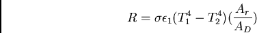 |
(9) |
 is the absolute temperature of the body,
  is the
temperature of the room,
is the
temperature of the room,  is the emittance of the body
(approx. ), and the ratio
is the emittance of the body
(approx. ), and the ratio
 compares the
area exchanging radiative energy with the surroundings (
compares the
area exchanging radiative energy with the surroundings ( ) to the
total body surface area (). This ratio is
) to the
total body surface area (). This ratio is  for a body
sitting and
for a body
sitting and  for a body standing. The max value is for a
body spread eagled. Thus, for a naked man sitting in a room,
for a body standing. The max value is for a
body spread eagled. Thus, for a naked man sitting in a room,
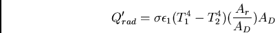 |
(10) |
 |
(11) |
 |
(12) |
 . Similarly, in a
  room,
room,  of dissipation
may be expected.
of dissipation
may be expected.
Heat may also be re-gained by the body through radiation, in
particular, solar radiation. Human skin and clothing have variable
emissivity for many of the wavelengths generated by the sun (a
 source). In addition, the angle of the sun and orientation
of the subject have significant effects on the heat transfer.
However, empirical studies have shown that a semi-nude man walking in
a desert has an effective
source). In addition, the angle of the sun and orientation
of the subject have significant effects on the heat transfer.
However, empirical studies have shown that a semi-nude man walking in
a desert has an effective  solar load. When light colored
clothing is worn, this can be lessened to
solar load. When light colored
clothing is worn, this can be lessened to  [73].
[73].
Normally, conduction plays a small role in human heat regulation,
except as the first stage of convection. Heat can be dissipated
through contact with shoe soles, doorknobs, or through the surface
underneath a reclining subject. Heat conduction through a plate of
area and thickness is given by
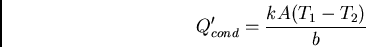 |
(13) |
where  is the thermal conductivity of the plate and
and are the temperatures on either side of the plate. The sign
of
indicates direction of heat flow. Table
8.1, adapted from Clark [36] and Ozisik
[158], lists the thermal conductivity of some useful
materials.
is the thermal conductivity of the plate and
and are the temperatures on either side of the plate. The sign
of
indicates direction of heat flow. Table
8.1, adapted from Clark [36] and Ozisik
[158], lists the thermal conductivity of some useful
materials.
When the body is sedentary, it loses heat during evaporation of water
from the respiratory tract and from diffusion of water vapor through the skin
(insensible or latent heat loss). When other modes of heat loss are
insufficient, the body sheds excess heat through evaporation of sweat
(sensible heat loss). The rate of heat lost through the
evaporation process can be calculated by
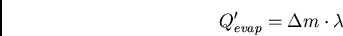 |
(14) |
 is the rate of mass of water lost and is
the latent heat of evaporation of sweat (
is the rate of mass of water lost and is
the latent heat of evaporation of sweat (
 ). Thus,
for the typical water loss of
). Thus,
for the typical water loss of
 through the
respiratory tract, the heat loss is
through the
respiratory tract, the heat loss is  . In hot environments, sweat
rates can be as high as
. In hot environments, sweat
rates can be as high as
 for unacclimatized persons
and
for unacclimatized persons
and
 for acclimatized persons, resulting in
  to of heat dissipation respectively [36,233].
In this sense, humans are at the extreme of evaporative heat
dissipation in the animal kingdom - sweat evaporation is of much
higher importance than panting [152].
to of heat dissipation respectively [36,233].
In this sense, humans are at the extreme of evaporative heat
dissipation in the animal kingdom - sweat evaporation is of much
higher importance than panting [152].
Evaporation can be a very effective means of cooling in hot
environments and correspondingly, a danger in cool environments. Some
basic equations and an example will illustrate this.

 , air vapor pressure
  , the evaporative
coefficient
, the evaporative
coefficient  , and skin surface area . Such a maximum can be
defined because once the skin's surface is saturated, more sweating
does not produce increased heat loss.
, and skin surface area . Such a maximum can be
defined because once the skin's surface is saturated, more sweating
does not produce increased heat loss.
An approximation of the evaporative
coefficient can be derived from

 is air speed in and has units of

Atmospheric vapor pressure can be measured with wet and dry bulb
thermometers (see Houdas and Ring [95]), or it can be derived from standard
tables given air temperature and dew point or relative humidity [242].
For convenience, a good approximation (within 3%) of
vapor pressure for temperatures between  and is
 is the dew point (temperature at which the water
vapor will condense), and
is the dew point (temperature at which the water
vapor will condense), and  is in units of mmHg [60]
(
is in units of mmHg [60]
(
 ).
).
For example, imagine the average subject on a warm and humid summer
day at sea level with a pleasant breeze of
 . Air
temperature is
. Air
temperature is  (
( ), dew point is
  (corresponding
to relative humidity of 80%), and the subject's skin is already a
moderate (
(corresponding
to relative humidity of 80%), and the subject's skin is already a
moderate ( ), cooled by the evaporation of sweat. Thus,
the moist skin and saturated air boundary have a vapor pressure of
), cooled by the evaporation of sweat. Thus,
the moist skin and saturated air boundary have a vapor pressure of

 is
is
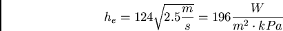

Note from these equations that a drop in air temperature or humidity
can have large effects on potential heat dissipation. For example,
assuming the same conditions, but with a dew point of  from a
drop in relative humidity to 25%, the vapor pressure becomes
from a
drop in relative humidity to 25%, the vapor pressure becomes
 , resulting in a maximum heat loss of 1400W! This dramatic
result shows the importance of keeping warm when sedentary after long
periods of strenuous exercise. Of course, an equivalent way to get a
dew point is for the ambient temperature to be with a
relative humidity of 100%. Thus, even relatively moderate
temperatures can be dangerous without protection from precipitation.
, resulting in a maximum heat loss of 1400W! This dramatic
result shows the importance of keeping warm when sedentary after long
periods of strenuous exercise. Of course, an equivalent way to get a
dew point is for the ambient temperature to be with a
relative humidity of 100%. Thus, even relatively moderate
temperatures can be dangerous without protection from precipitation.
We have shown that different heat dissipation mechanisms dominate the body's heat output depending on sweat, skin temperature, and ambient temperature. However, what can be said about the heat output of the human body on average? As a first approximation, an average caloric food intake (2500 Calories) can be used to calculate an average heat output per day of 121W [207]. Note that this ignores energy that leaves the body as fecal mass and urine and any ``useful'' work done by the body (work that stores potential). However, given that the maximum mechanical efficiency of the human body is approximately 20% [73] and, averaged over the day, ``useful'' work becomes negligible, the approximation seems sound.
Given the 121W generated by converting food to power, how is heat dissipation divided among the different cooling mechanisms over an extended period? Table 8.2, adapted from Evans [59] in Clark [36], shows heat loss values for an adult man over 24 hours with no sensible water loss.
One term in equation 8.1 is still unexamined:
.
Heat storage in the body takes the form of a higher body temperature
and can be calculated with the formula
 |
(15) |
is the energy stored, is body mass,  is the specific
heat of the body (approx.
is the specific
heat of the body (approx.
 ), and
 is the change in body temperature. Thus, for a
  increase in a man,
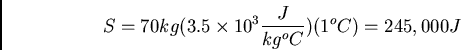 |
(16) |
 . In this way
the human body is its own buffer when adequate heat dissipation is
not available or, conversely, when too much heat is being dissipated.
. In this way
the human body is its own buffer when adequate heat dissipation is
not available or, conversely, when too much heat is being dissipated.
For the purposes of this paper, two kinds of thermal comfort will be considered. On the macro scale, environment temperatures at which subjects feel comfortable, or the ``comfort zone,'' will be discussed. It is necessary to consider when the computer or electronics add a significant amount of heat to the user's thermal environment or are positioned so as to affect the user's normal modes of heat dissipation. The second section is more concerned with appropriate temperatures for direct skin contact, the neuroscience involved in thermal sensation, and potential damage due to high temperatures.
Comfort depends upon body and skin temperature, with skin temperature
often playing a dominate role. For the USA and UK, the comfort zone
is considered to be  to
to  with air movement less than
 and relative humidity between 30 and 70%. However,
due to the many factors involved, these values are often inconsistent
in the literature. Ducharme
[52] found that subjects dressed in t-shirts and pants
were most comfortable at with a relative humidity of 40%.
However, some studies have found preferred temperatures ranging from
and relative humidity between 30 and 70%. However,
due to the many factors involved, these values are often inconsistent
in the literature. Ducharme
[52] found that subjects dressed in t-shirts and pants
were most comfortable at with a relative humidity of 40%.
However, some studies have found preferred temperatures ranging from
 to . Reasons given for this variability include fashion,
sex, native climate conditions, metabolic rate, and age. Conversely,
careful studies by Fanger, Nevins, and McNall [60] in a
climatic chamber show that environmental conditions for comfort were
virtually the same for all subjects. From these studies, the
researchers have drawn up charts detailing comfortable ambient
temperature taking into account different activities and levels of
clothing. In addition, these researchers develop a ``comfort equation''
which must be balanced for thermal comfort based from studies of
college-age Americans in steady state conditions (exposure longer than
1-2 hours).
to . Reasons given for this variability include fashion,
sex, native climate conditions, metabolic rate, and age. Conversely,
careful studies by Fanger, Nevins, and McNall [60] in a
climatic chamber show that environmental conditions for comfort were
virtually the same for all subjects. From these studies, the
researchers have drawn up charts detailing comfortable ambient
temperature taking into account different activities and levels of
clothing. In addition, these researchers develop a ``comfort equation''
which must be balanced for thermal comfort based from studies of
college-age Americans in steady state conditions (exposure longer than
1-2 hours).
![\begin{displaymath}\frac{M}{A_D} - 0.35[43 - 0.061 \cdot \frac{M}{A_D}(1 - \nu) - p_a]
\end{displaymath}](img325.png)

![\begin{displaymath}4.8 \times 10^{-8} \cdot f_{cl} \cdot
f_{eff}[(T_{xl} + 273)^4 - (T_{mrt} + 273)^4] + f_{cl} \cdot h_c(T_{cl} - T_a) \end{displaymath}](img327.png)
where is DuBois surface area, water vapor pressure,  metabolic rate,
  air temperature,
  clothing surface
temperature,
clothing surface
temperature,  experimental mechanical efficiency, and
  mean
radiant temperature.
mean
radiant temperature.  is the ratio of the surface area of the
clothed body to that of the nude body, and
is the ratio of the surface area of the
clothed body to that of the nude body, and  (
in previous sections) is the ratio of the effective radiation area of
the clothed body to the surface area of the clothed body. is the
convective cooling coefficient as first described in the
convection section above. Constants in this equation were converted
from the original source using the ratio
(
in previous sections) is the ratio of the effective radiation area of
the clothed body to the surface area of the clothed body. is the
convective cooling coefficient as first described in the
convection section above. Constants in this equation were converted
from the original source using the ratio
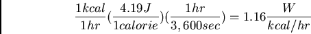
Outside of the comfort range, heat stress can have adverse effects.
In general, the body's core temperature is kept close to and
variations  affect body functions and task performance.
Variations of
affect body functions and task performance.
Variations of  are usually fatal. However, small rises in
body temperature may not impair all tasks. For
example, in auditory vigilance tasks where the subject had to detect
auditory tones, more signals were detected after a increase
in body temperature. In addition, workers skilled in a given task seem
more immune to slightly increased temperatures than workers new or
semi-trained in a task. In order to begin to quantify the effects of
environmental conditions, heat stress indices have been proposed
including ``effective temperature'' and the ``wind chill index.''
Most methods integrate wet and dry bulb temperatures and wind
velocities in an experimentally determined chart designed
to compare one set of conditions to another. Each has its strengths,
weakness, and ranges of appropriate conditions. For a review see
Clark [36].
are usually fatal. However, small rises in
body temperature may not impair all tasks. For
example, in auditory vigilance tasks where the subject had to detect
auditory tones, more signals were detected after a increase
in body temperature. In addition, workers skilled in a given task seem
more immune to slightly increased temperatures than workers new or
semi-trained in a task. In order to begin to quantify the effects of
environmental conditions, heat stress indices have been proposed
including ``effective temperature'' and the ``wind chill index.''
Most methods integrate wet and dry bulb temperatures and wind
velocities in an experimentally determined chart designed
to compare one set of conditions to another. Each has its strengths,
weakness, and ranges of appropriate conditions. For a review see
Clark [36].
When unchecked, heat stress can cause several medical conditions. For the purposes of this paper, the most important is heat rash, which results from inflammation of the sweat glands when perspiration is not removed from the skin. When designing electronic systems for more extreme conditions, such as in firefighting or the military, conditions such as heat fatigue, fainting, heat exhaustion, heat syncope, and heat stroke must be considered.
while the forehead is  [110]. Even temperatures within a small region may show
significant variation due to air flow [36]. How these
temperatures are perceived by the body depends on the range and the
context of the temperatures.
There are at least three different types of thermal receptors: warm,
cold, and pain. Thermal receptors have a stimulatory diameter of
about 1mm and can be relatively scarce in the surface of the skin.
Cold receptors vary from 15-25 points per square centimeter in the
lips, 3-5 in the finger, and less than 1 in broad surfaces such as the
trunk. Warm receptors are 3-10 times less dense. Warm and cold
receptors are stimulated by the change in their metabolic rates caused
by the change in temperature and are thus relatively slow sensors.
However, cold receptors use faster neural transmission systems.
Thermal sensation is spatially summed. Changes as small as
[110]. Even temperatures within a small region may show
significant variation due to air flow [36]. How these
temperatures are perceived by the body depends on the range and the
context of the temperatures.
There are at least three different types of thermal receptors: warm,
cold, and pain. Thermal receptors have a stimulatory diameter of
about 1mm and can be relatively scarce in the surface of the skin.
Cold receptors vary from 15-25 points per square centimeter in the
lips, 3-5 in the finger, and less than 1 in broad surfaces such as the
trunk. Warm receptors are 3-10 times less dense. Warm and cold
receptors are stimulated by the change in their metabolic rates caused
by the change in temperature and are thus relatively slow sensors.
However, cold receptors use faster neural transmission systems.
Thermal sensation is spatially summed. Changes as small as
 can be detected if an entire surface is affected, but
changes of might go undetected in an area the size of a square
centimeter. Thermal receptors adapt to a given thermal state, but not
completely. After an initial impulse, the sensation dies down but
does not go away. A rise or fall in temperature has a greater
perceived effect than a constant temperature. For example, a person
will feel warmer at a given temperature if, in the recent past, the
temperature has been rising. Extremes of cold or hot stimulate the
pain receptors. Paradoxically, the pain sensation from a hot surface
feels the same as that from a cold surface [84].
Table 8.3, adapted from Gagge and Gonzalez [73], summarizes typical responses to skin
temperatures. The receptors in the skin are much more
sensitive to changes in temperatures. Thus, momentary contact with a
surface that is warmer than the skin will elicit a sensation that
seems much hotter than would be felt with more constant contact.
This, plus the fact that skin can be quite cool compared to normal
body temperature, corresponds to the wide bounds on these ranges.
can be detected if an entire surface is affected, but
changes of might go undetected in an area the size of a square
centimeter. Thermal receptors adapt to a given thermal state, but not
completely. After an initial impulse, the sensation dies down but
does not go away. A rise or fall in temperature has a greater
perceived effect than a constant temperature. For example, a person
will feel warmer at a given temperature if, in the recent past, the
temperature has been rising. Extremes of cold or hot stimulate the
pain receptors. Paradoxically, the pain sensation from a hot surface
feels the same as that from a cold surface [84].
Table 8.3, adapted from Gagge and Gonzalez [73], summarizes typical responses to skin
temperatures. The receptors in the skin are much more
sensitive to changes in temperatures. Thus, momentary contact with a
surface that is warmer than the skin will elicit a sensation that
seems much hotter than would be felt with more constant contact.
This, plus the fact that skin can be quite cool compared to normal
body temperature, corresponds to the wide bounds on these ranges.
While contact with any surface above  for an extended period of
time risks burning, temporary contact can be made at higher
temperatures. For
for an extended period of
time risks burning, temporary contact can be made at higher
temperatures. For  minutes, contact with a surface at a temperature
of
minutes, contact with a surface at a temperature
of  can be maintained. Metals and water at
  can be in
contact with the skin for minute without a burn risk. In addition,
concrete can be tolerated for minute at
can be in
contact with the skin for minute without a burn risk. In addition,
concrete can be tolerated for minute at  , and plastics and
wood at
, and plastics and
wood at  . At higher temperatures and shorter contact times,
materials show a higher differentiation of burn risk [110]
. At higher temperatures and shorter contact times,
materials show a higher differentiation of burn risk [110]
While the previous section discussed rules and principles in general, this section will concentrate on a specific example: a forearm-mounted wearable computer (inspired by BT's proposed ``Office on the Arm'' [239]). The goal is to model how much heat such a computer could generate if it is thermally coupled to the user. In order to perform this analysis, several conditions must be assumed.
First, the surface area of the forearm must be approximated. The
forearm is about  of the body's surface area [73] or
 for our assumed user. Note that this is approximately the
surface area of the bottom of a smaller notebook computer. For
convenience, it will be assumed that the computer fits snugly around
the forearm as a sleeve for near perfect heat conduction and will have
negligible thickness so that inner and outer surface areas will be
approximately equal. The reader should note that increasing the
thickness of the sleeve also increases heat exchange from exposing
a larger surface area to the environment.
for our assumed user. Note that this is approximately the
surface area of the bottom of a smaller notebook computer. For
convenience, it will be assumed that the computer fits snugly around
the forearm as a sleeve for near perfect heat conduction and will have
negligible thickness so that inner and outer surface areas will be
approximately equal. The reader should note that increasing the
thickness of the sleeve also increases heat exchange from exposing
a larger surface area to the environment.
To provide an approximate bounds on the amount of heat the forearm
computer can generate, the free air dissipation of heat through
convection and radiation must be calculated. For practical
considerations, the assumed environment will be a relatively warm,
humid day of (), relative humidity of 80%, and a
maximum allowable surface temperature of the computer of  .
was chosen as a ``safe'' temperature based on a summary of
the medical literature by Lele on observable tissue damage after timed
heat exposure [23,119], a survey of heat shock
protein (HSP) studies which use
.
was chosen as a ``safe'' temperature based on a summary of
the medical literature by Lele on observable tissue damage after timed
heat exposure [23,119], a survey of heat shock
protein (HSP) studies which use  water baths to encourage
HSP production [53], and many reported physiological
experiments where subjects were immersed in water baths for several
hours at significantly higher temperatures
[12,181,230]. Furthermore, similar
temperatures can be measured from the bottom surfaces of modern
notebook computers.
water baths to encourage
HSP production [53], and many reported physiological
experiments where subjects were immersed in water baths for several
hours at significantly higher temperatures
[12,181,230]. Furthermore, similar
temperatures can be measured from the bottom surfaces of modern
notebook computers.
Using the guidelines from above
 |
(17) |
 |
(18) |
 |
(19) |
 and 80% of the surface of the
forearm computer ``seeing'' the environment for radiative exchange
and 80% of the surface of the
forearm computer ``seeing'' the environment for radiative exchange
 |
(20) |
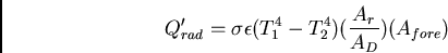 |
(21) |
 |
(22) |
 |
(23) |
 |
(24) |
Thus, in this environment, uncoupled from the body with no wind and no
body motion, the forearm computer is limited to  . From these
calculations, a notebook computer could dissipate
. From these
calculations, a notebook computer could dissipate  , having
approximately twice the surface area. Note that this is in agreement
with the to
, having
approximately twice the surface area. Note that this is in agreement
with the to  heat production characteristic of passively cooled
notebook computers common in 1994 and 1995. As an aside, Intel
guidelines increase the heat limit to
heat production characteristic of passively cooled
notebook computers common in 1994 and 1995. As an aside, Intel
guidelines increase the heat limit to  to
to  for notebook computers
with aggressive active cooling [145].
for notebook computers
with aggressive active cooling [145].
Once mounted on the arm, heat will be conducted from the
computer to the arm. Most thermal coupling occurs
through the skin to the surface veins and arteries. Skin has a
thermal conductivity of
 , and the
body will maintain a temperature of
, and the
body will maintain a temperature of  for blood coming from
the body's core. However, the linear heat conduction equation above is
inadequate for modeling the heat transport of the
blood stream. In order to proceed in creating an appropriate model, the first
step is to determine the rate of blood flow through the forearm.
for blood coming from
the body's core. However, the linear heat conduction equation above is
inadequate for modeling the heat transport of the
blood stream. In order to proceed in creating an appropriate model, the first
step is to determine the rate of blood flow through the forearm.
The primary means of thermoregulation by the human body is the re-routing of blood flow from deeper blood vessels to more superficial skin vessels, or vice versa. Table 8.4 (from [29]) shows the approximate depths of skin blood vessels. Skin blood flow is increased to an area when the local temperature of that part is raised, when an irritant is applied, or when the body temperature as a whole is elevated [36]. In addition, if there is a sufficient rise in return blood temperature from a peripheral body part, the body as a whole will begin heat dissipation measures [13,50]. However, it is improbable that enough heat would be transfered via one forearm to incite such a response [105].
Skin blood flow is regulated by vasodilation and vasoconstriction
nerves. Areas that act as heat sinks, like the hands
[106], have almost exclusively vasoconstriction nerves.
In these areas, the arterial flow into the area must be warm already
to cause the relaxation of vasoconstriction. Larger areas, such as
the forearm, have a mixture of vasodilators and vasconstrictors,
making the prediction of skin blood flow difficult. However,
empirical studies by Taylor et al. [230] suggest that
maximum forearm blood flow occurs when the forearm skin is raised to
 for
for  minutes. While there can be considerable
variability among subjects depending on age, weight, blood pressure,
and other factors, Taylor et al. found in their measurements that the
average maximum skin blood flow in the forearm is
minutes. While there can be considerable
variability among subjects depending on age, weight, blood pressure,
and other factors, Taylor et al. found in their measurements that the
average maximum skin blood flow in the forearm is
 .
.
This last set of units requires some explanation. In physiology
literature, blood flow is normalized for the volume of tissue in which
it is observed. In this case, the tissue is a volume of the forearm.
In many experiments, total forearm blood flow is measured, which
includes blood flow through both skeletal muscle and skin. However,
muscle blood flow does not change significantly with outside
application of heat to the forearm [48,54,186].
Thus, as above, results are sometimes given in skin blood flow instead
of total blood flow per volume of forearm [182]. Johnson
and Proppe [106] provide a conversion factor: 100ml of
forearm roughly corresponds to  of skin. Combining this
figure with the specific heat of blood
of skin. Combining this
figure with the specific heat of blood
 and its density
 [19] yields a
striking maximum heat dissipation capability of the blood in the
forearm of
[19] yields a
striking maximum heat dissipation capability of the blood in the
forearm of
 |
(25) |
 [106]. Armed with
these results, we can create a model for heat
conduction in the forearm.
[106]. Armed with
these results, we can create a model for heat
conduction in the forearm.
We ![]() model the arm as a set of four concentric cylinders of increasing
radius, based on the information in Table 8.4 (see
Chato [33], Pardasani and Adlakha [159], and
Roetzel and Xuan [178] for related bioheat models). Figure
8-2 demonstrates the variables used in this derivation.
Blood originates from the body (at ) flows through the
arterial layer and returns through the two venous layers. This model
is similar to the double-pipe bayonet heat exchanger developed in
Martin's Heat Exchangers [133].
model the arm as a set of four concentric cylinders of increasing
radius, based on the information in Table 8.4 (see
Chato [33], Pardasani and Adlakha [159], and
Roetzel and Xuan [178] for related bioheat models). Figure
8-2 demonstrates the variables used in this derivation.
Blood originates from the body (at ) flows through the
arterial layer and returns through the two venous layers. This model
is similar to the double-pipe bayonet heat exchanger developed in
Martin's Heat Exchangers [133].
To begin, we define the fundamental heat flow rates in the arm.
 is the heat capacity of the blood. We define the heat flow
rates as
is the heat capacity of the blood. We define the heat flow
rates as
 is the temperature of the external heat bath,
  is
the temperature of the inner arm, and , , and
is
the temperature of the inner arm, and , , and  are the
blood temperatures between the cylinders.
are the
blood temperatures between the cylinders.  ,
,  ,
,  , and
, and
 are the areas of the outer to inner cylinders, respectively.
 is a cylindrical shell of blood layer of length
  over
which one considers the differential heat flow rates across that
surface.
over
which one considers the differential heat flow rates across that
surface.
Equation 8.32 was set to zero to simplify the
calculation. Since blood mass is conserved, arterial blood flow must
return along the two venous layers. We can thus define the blood flow
rates as
 .
.
To ease the computation, the above equations can be reformulated in
terms of dimensionless parameters. Define
 ,
,
 ,
,
 ,
,
 ,
,
 where is the total length of the arm. Combining this with equations
8.26 through 8.34 yields
where is the total length of the arm. Combining this with equations
8.26 through 8.34 yields
Let
 .
.  is a constant to denote the temperature of the blood in the rest of the body as it flows into the artery of the arm. The derivative is
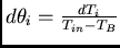 . Finally this yields three dimensionless, coupled differential equations
The general solution is of the form
Equations 8.38 - 8.40 can easily be decoupled in a
matrix formalism. Rewriting the right side of equations
8.38 through 8.40 as a matrix, , the
eigenvalues of are the  's. Thus, solving the cubic
equation
's. Thus, solving the cubic
equation
.
The remaining part of the solution entails applying the boundary conditions. The boundary conditions are:
 C.
C.
 ,
,
The same can be done with the second boundary condition, occurring at  (and
(and  ),
),
![\begin{displaymath}
M = \left[ \begin{array}{ccccccccc}
0 & 0 & 0 & 1 & 1 & 1 & ...
...lambda_2\!\!&\!\!\upsilon_{3}\lambda_3\!\!
\end{array} \right]
\end{displaymath}](img456.png) |
(60) |
![\begin{displaymath}
C = \left[ \begin{array}{c}
C_{1,1} \\ C_{1,2} \\ C_{1,3} \\...
...+\beta \\ q\beta \\ 0 \\ 0 \\ 0 \\ 0 \\ 0
\end{array} \right]
\end{displaymath}](img457.png) |
(61) |
 ,
,
 ,
,
 , and
, and
 . The constants become
 and a final solution is obtained.
The actual physical data used to solve this problem are listed below:
=37C, =39C.
 [1].
[1].
 ,
,
 , and
, and
 .
.
 and the average
radius of the forearm is 0.035 m [36].
and the average
radius of the forearm is 0.035 m [36].
 ,,
,, , and
, and 
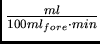 ) [36].
The average
power transfer into the arm can be calculated by taking the mean
integral of the temperature distribution in the outer vein and
modifying equation 8.31:
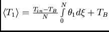
The power results for the different blood flows are shown in Table 8.5.
While this derivation was performed for an applied temperature  , the power rating increases linearly with the difference
between the applied temperature and body temperature. Thus, at the
hypothetical
, the power rating increases linearly with the difference
between the applied temperature and body temperature. Thus, at the
hypothetical  , which should develop very close to maximum
skin blood flow, we expect around 28W of heat conduction through the
forearm.
, which should develop very close to maximum
skin blood flow, we expect around 28W of heat conduction through the
forearm.
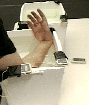 |
To verify the model in the last section, I devised an experiment to
examine the conduction of heat away from the forearm's surface. For
calibration, five digital thermometers were placed in a small,
stirred, and temperature-controlled water bath. Readings were taken
for various temperatures expected during the experiment, and the
resulting offsets calculated from the average can be seen in Table
8.6. Two open-topped liter styrofoam containers were
filled with tap water at  and placed side by side in a
temperature-controlled room. Magnetic stirrers were used to
keep the water agitated. Two calibrated thermometers were placed
diagonally across from each other in each bath. In addition, mercury
and alcohol laboratory thermometers indicated when the baths cooled to
to signal the start of the experiment. This temperature is
the upper bound on the calibrated thermometers' effective ranges as
well as the temperature often used in the background literature for
forearm water baths. For the control bath, the mercury thermometer as
well as thermometers 1 and 4 were used, while the rest of the
thermometers were used for the arm bath. At , the subject
immersed his forearm into the ``forearm bath,'' leaving his upper arm
and hand out of the bath (see Figure 8-3). The
temperatures of both the forearm and control baths were recorded every
and placed side by side in a
temperature-controlled room. Magnetic stirrers were used to
keep the water agitated. Two calibrated thermometers were placed
diagonally across from each other in each bath. In addition, mercury
and alcohol laboratory thermometers indicated when the baths cooled to
to signal the start of the experiment. This temperature is
the upper bound on the calibrated thermometers' effective ranges as
well as the temperature often used in the background literature for
forearm water baths. For the control bath, the mercury thermometer as
well as thermometers 1 and 4 were used, while the rest of the
thermometers were used for the arm bath. At , the subject
immersed his forearm into the ``forearm bath,'' leaving his upper arm
and hand out of the bath (see Figure 8-3). The
temperatures of both the forearm and control baths were recorded every
 seconds until the baths cooled below body temperature. Table
8.8 shows the values recorded, and Table
8.9 provides average readings and the standard
deviations for both the control and arm baths. The mercury and
alcohol thermometer readings are not used for these calculations as
these thermometers were used simply to indicate when the digital
thermometers would be within their specified range. The subject was
dressed in t-shirt, jeans, and boots. Before the experiment, the
subject indicated he was overly warm even after remaining seated for
an hour. Before and during the experiment, his body temperature
remained constant and no visible perspiration was evident, though he
claimed his forehead felt moist before immersion and during the early
part of the experiment. This would seem to indicate the subject was
near his physiological tolerance to heat before resorting to open
sweating.
seconds until the baths cooled below body temperature. Table
8.8 shows the values recorded, and Table
8.9 provides average readings and the standard
deviations for both the control and arm baths. The mercury and
alcohol thermometer readings are not used for these calculations as
these thermometers were used simply to indicate when the digital
thermometers would be within their specified range. The subject was
dressed in t-shirt, jeans, and boots. Before the experiment, the
subject indicated he was overly warm even after remaining seated for
an hour. Before and during the experiment, his body temperature
remained constant and no visible perspiration was evident, though he
claimed his forehead felt moist before immersion and during the early
part of the experiment. This would seem to indicate the subject was
near his physiological tolerance to heat before resorting to open
sweating.
| Trial | Sensor1 | Sensor2 | Sensor3 | Sensor4 | Sensor5 | Ave. |
| 1 | 36.75 | 36.71 | 36.76 | 36.76 | 36.81 | 36.76 |
| 2 | 37.94 | 37.87 | 37.94 | 37.95 | 37.99 | 37.94 |
| 3 | 42.57 | 42.45 | 42.54 | 42.54 | 42.59 | 42.54 |
| 4 | 34.15 | 34.10 | 34.14 | 34.14 | 34.19 | 34.14 |
| 5 | 36.67 | 36.64 | 36.67 | 36.69 | 36.78 | 36.69 |
| 6 | 39.31 | 39.24 | 39.30 | 39.29 | 39.35 | 39.30 |
| 7 | 40.00 | 39.94 | 40.01 | 40.00 | 40.07 | 40.00 |
| 8 | 40.87 | 40.79 | 40.87 | 40.85 | 40.93 | 40.86 |
| offset | 0.00 | 0.06 | 0.00 | 0.00 | -0.06 |
| Control | Arm | |||||
| Time | Sensor1 | Sensor4 | Mercury | Sensor2 | Sensor3 | Alcohol |
| (sec) | ( ) ) |
() |
() |
() |
() |
() |
| 0 | 42.58 | 42.65 | 42.60 | 42.98 | -.- | 43.00 |
| 200 | 42.13 | 42.23 | 42.20 | 42.43 | 42.57 | 42.00 |
| 400 | 41.70 | 41.75 | 41.60 | 41.91 | 42.04 | 41.00 |
| 600 | 41.31 | 41.31 | 41.40 | 41.45 | 41.50 | 41.00 |
| 800 | 40.86 | 40.93 | 41.00 | 41.12 | 40.92 | 40.50 |
| 1000 | 40.46 | 40.48 | 40.60 | 40.49 | 40.59 | 40.00 |
| 1200 | 40.11 | 40.13 | 40.20 | 40.28 | 40.05 | 39.50 |
| 1400 | 39.77 | 39.79 | 39.80 | 39.79 | 39.88 | 39.20 |
| 1600 | 39.39 | 39.44 | 39.50 | 39.44 | 39.53 | 38.80 |
| 1800 | 39.06 | 39.11 | 39.10 | 39.11 | 39.19 | 38.50 |
| 2000 | 38.77 | 38.77 | 38.70 | 38.79 | 38.89 | 38.00 |
| 2200 | 38.44 | 38.50 | 38.40 | 38.51 | 38.62 | 37.50 |
| 2400 | 38.08 | 38.14 | 38.00 | 38.21 | 38.31 | 37.00 |
| 2600 | 37.79 | 37.81 | 37.80 | 37.95 | 38.05 | 37.00 |
| 2800 | 37.52 | 37.52 | 37.40 | 37.68 | 37.79 | 36.50 |
| 3000 | 37.21 | 37.26 | 37.20 | 37.45 | 37.57 | 36.50 |
| 3200 | 36.91 | 36.95 | 36.90 | 37.22 | 37.30 | 36.00 |
| 3400 | 36.61 | 36.67 | 36.80 | 37.01 | 37.05 | 36.00 |
| 3600 | 36.31 | 36.35 | 36.40 | 36.74 | 36.82 | 35.80 |
| 3800 | 36.07 | 36.11 | 36.00 | 36.55 | 36.64 | 35.70 |
| Time | Ave. control | Ave. arm | SD control | SD arm |
( ) ) |
() |
() |
() |
() |
| 0 | 42.61 | 42.98 | 0.05 | 0.00 |
| 200 | 42.18 | 42.50 | 0.07 | 0.10 |
| 400 | 41.72 | 41.98 | 0.04 | 0.09 |
| 600 | 41.31 | 41.48 | 0.00 | 0.03 |
| 800 | 40.89 | 41.02 | 0.05 | 0.14 |
| 1000 | 40.47 | 40.54 | 0.02 | 0.07 |
| 1200 | 40.12 | 40.17 | 0.02 | 0.16 |
| 1400 | 39.78 | 39.84 | 0.02 | 0.06 |
| 1600 | 39.41 | 39.49 | 0.04 | 0.06 |
| 1800 | 39.08 | 39.15 | 0.04 | 0.06 |
| 2000 | 38.77 | 38.84 | 0.00 | 0.07 |
| 2200 | 38.47 | 38.57 | 0.05 | 0.08 |
| 2400 | 38.11 | 38.26 | 0.05 | 0.07 |
| 2600 | 37.80 | 38.00 | 0.02 | 0.07 |
| 2800 | 37.52 | 37.74 | 0.00 | 0.08 |
| 3000 | 37.23 | 37.51 | 0.04 | 0.08 |
| 3200 | 36.93 | 37.26 | 0.03 | 0.06 |
| 3400 | 36.64 | 37.03 | 0.05 | 0.03 |
| 3600 | 36.33 | 36.78 | 0.03 | 0.06 |
| 3800 | 36.09 | 36.60 | 0.03 | 0.06 |
| Ave. | 0.03 | 0.07 |
For each second time period, the heat loss of each bath was
calculated using the temperature corrected thermal capacity of water
(see Table 8.7 [242]). Table
8.10 shows the average temperature of the
control bath during each second period versus the calculated
heat loss during that period. Table 8.11 shows a
similar table for the forearm bath but also includes the heat loss for
the control bath interpolated to the temperature of the forearm bath.
The last entry of the table shows the difference in heat loss between
the control and forearm baths. Figure 8-4 plots the
heat losses for both baths during the experiment and Figure
8-5 shows the increase in heat dissipation caused
by conduction through the forearm.
| Time | Ave. temp. | Heat loss |
| (sec) | control bath () |
( ) ) |
| 200 | 42.40 | 18178.65 |
| 400 | 41.95 | 19014.45 |
| 600 | 41.52 | 17342.85 |
| 800 | 41.10 | 17342.85 |
| 1000 | 40.68 | 17760.75 |
| 1200 | 40.29 | 14626.50 |
| 1400 | 39.95 | 14208.60 |
| 1600 | 39.60 | 15253.35 |
| 1800 | 39.25 | 13790.70 |
| 2000 | 38.93 | 13163.85 |
| 2200 | 38.62 | 12537.00 |
| 2400 | 38.29 | 15040.80 |
| 2600 | 37.95 | 12951.80 |
| 2800 | 37.66 | 11698.40 |
| 3000 | 37.38 | 11907.30 |
| 3200 | 37.08 | 12742.90 |
| 3400 | 36.78 | 12116.20 |
| 3600 | 36.48 | 12951.80 |
| 3800 | 36.21 | 10027.20 |
| Time | Ave. temp | Arm bath | Norm. control | Heat loss difference |
| (sec) | arm bath () |
heat loss () |
bath heat loss () |
via conduction ( ) ) |
| 200 | 42.74 | 20085.32 | 17531.26 | 12.77 |
| 400 | 42.24 | 21939.75 | 18475.64 | 17.32 |
| 600 | 41.73 | 20895.00 | 18147.43 | 13.74 |
| 800 | 41.25 | 19014.45 | 17342.85 | 8.36 |
| 1000 | 40.78 | 20059.20 | 17661.87 | 11.99 |
| 1200 | 40.35 | 15671.25 | 15106.75 | 2.82 |
| 1400 | 40.00 | 13790.70 | 14271.44 | -2.40 |
| 1600 | 39.66 | 14626.50 | 15062.55 | -2.18 |
| 1800 | 39.32 | 13999.65 | 14082.70 | -0.42 |
| 2000 | 39.00 | 12954.90 | 13298.70 | -1.72 |
| 2200 | 38.70 | 11492.25 | 12709.00 | -6.08 |
| 2400 | 38.41 | 12742.90 | 14097.13 | -6.77 |
| 2600 | 38.13 | 10862.80 | 14054.76 | -15.96 |
| 2800 | 37.87 | 11071.70 | 12588.00 | -7.58 |
| 3000 | 37.62 | 9400.50 | 11724.74 | -11.62 |
| 3200 | 37.39 | 10445.00 | 11724.74 | -6.40 |
| 3400 | 37.15 | 9609.40 | 11880.74 | -11.36 |
| 3600 | 36.91 | 10445.00 | 12878.51 | -12.17 |
| 3800 | 36.69 | 7729.30 | 11776.74 | -20.24 |
Note that a ``knee'' occurs in Figure 8-5 at
approximately  . Above this temperature, the forearm bath
seems to dissipate, on average,
. Above this temperature, the forearm bath
seems to dissipate, on average,  more than the control bath.
Under
more than the control bath.
Under  the forearm bath is actually dissipating less than the
control bath. Such a drastic change would be expected around ,
when the subject's body could be heating the water, but why would such
a sudden change happen around ? First, the amount of blood
that is pumped to the surface veins and arteries of the forearm
decreases as temperature decreases. A similar breakpoint is observed
in the literature [12] for blood flow at this
temperature. However, even given that the blood flow may be
significantly reduced at these temperatures, why should the presence
of the forearm inhibit heat dissipation before the water bath reaches
body temperature? Obviously, since the subject's body temperature did
not exceed , the forearm could not be adding heat to the
bath. Instead, the forearm likely blocked the natural radiative,
convective, and evaporative heat dissipation of the bath. To
compensate for this effect, the results must be offset by a minimum of
the forearm bath is actually dissipating less than the
control bath. Such a drastic change would be expected around ,
when the subject's body could be heating the water, but why would such
a sudden change happen around ? First, the amount of blood
that is pumped to the surface veins and arteries of the forearm
decreases as temperature decreases. A similar breakpoint is observed
in the literature [12] for blood flow at this
temperature. However, even given that the blood flow may be
significantly reduced at these temperatures, why should the presence
of the forearm inhibit heat dissipation before the water bath reaches
body temperature? Obviously, since the subject's body temperature did
not exceed , the forearm could not be adding heat to the
bath. Instead, the forearm likely blocked the natural radiative,
convective, and evaporative heat dissipation of the bath. To
compensate for this effect, the results must be offset by a minimum of
 , the difference between the baths at body temperature. This
figure provides a lower bounds because the limbs are often kept at a
temperature lower than the core temperature. Thus, the total
heat conducted away by the forearm is approximately
, the difference between the baths at body temperature. This
figure provides a lower bounds because the limbs are often kept at a
temperature lower than the core temperature. Thus, the total
heat conducted away by the forearm is approximately  at .
at .
This experimental result is significantly smaller than the predicted
 of the model. However, in the model we assumed that the
interior of the arm would be held constant at . In
actuality, the interior muscle mass of the arm will reach
of the model. However, in the model we assumed that the
interior of the arm would be held constant at . In
actuality, the interior muscle mass of the arm will reach  when the forearm is submerged in water at temperatures above
  [12,48]. With this change, the model predicts
approximately
[12,48]. With this change, the model predicts
approximately  of heat conduction, which closely matches the
experimental data. Other human limb heat transfer models that include
muscle heating have been published recently [178], but the
above model provides a simple predictive tool and is specifically
tailored for this task.
of heat conduction, which closely matches the
experimental data. Other human limb heat transfer models that include
muscle heating have been published recently [178], but the
above model provides a simple predictive tool and is specifically
tailored for this task.
While this experiment involved one subject, the results coincide with
temperature versus blood flow experiments from the literature and also
correlate nicely with the model proposed above. Note that since the
body is very active in maintaining its core temperature, similar
amounts of heat dissipation from the forearm may be available in all
but the most adverse conditions. Even at a more conservative forearm
temperature of , a substantial amount of heat will be
conducted away by the forearm as shown in the model above.
For future experiments, a thermally passive dummy arm of the same volume and heat capacity should be inserted into the control bath to compensate for the radiative, convective, and evaporative heat flow blocked by the subject's arm. In addition, the forearm bath measurements have an average standard deviation over twice that of the control bath. This indicates that the water baths should be agitated more aggressively. Finally, more subjects should be used in the experiment to verify the findings here and in the background literature.
Given the above models and calculations, a forearm computer may
generate up to
 |
(63) |
 versus
 ).
Unfortunately, this calculation ignores several practical factors.
Symbol has already shown the practicality of a lower power forearm
computer with an installed base of 30,000 units with United Parcel
Service [221]. However, with a higher power computer, would
the user feel that is too high a temperature for a sheath
on the forearm? A simple way to address this problem is to provide
the user with a physical knob to adjust the maximum operating
temperature of the computer (up to safe limits) and a meter showing
the fraction of full functionality available in current conditions.
This interface makes the trade-off between heat generation and
functionality explicit and accessible to the user.
).
Unfortunately, this calculation ignores several practical factors.
Symbol has already shown the practicality of a lower power forearm
computer with an installed base of 30,000 units with United Parcel
Service [221]. However, with a higher power computer, would
the user feel that is too high a temperature for a sheath
on the forearm? A simple way to address this problem is to provide
the user with a physical knob to adjust the maximum operating
temperature of the computer (up to safe limits) and a meter showing
the fraction of full functionality available in current conditions.
This interface makes the trade-off between heat generation and
functionality explicit and accessible to the user.
Another concern is sweating under the computer sleeve due to exertion. Without a way for sweat to be released, the user may experience discomfort similar to the sensation of sweating in rubber gloves. To alleviate this problem, a thin layer of heat conducting fabric can be used to ``wick'' the water trapped under the computer sleeve. Slits should be designed into the computer to allow evaporation of the water. The resulting evaporation will increase user comfort and increase cooling. The slits also provide the benefit of adding more surface area to the forearm computer, increasing cooling.
When an idle forearm computer is put on in the morning, initial exposure may cause a rapid heat loss in the forearm until the machine warms. In order to avoid such a chilling effect, the machine could be turned on and warmed before wearing. A more serious problem in cold weather is wearing the machine when it is not producing heat. While the above calculations assume a negligibly thin computer, in actuality the machine would increase the circumference of the arm and, therefore, its surface area. Thus, without the active warming of the machine, the wearer would actually lose more heat. Fortunately, the forearm would route blood through deeper veins as cooling increases. However, the sense of being ``cold'' comes more from the amount of heat being lost rather than the actual skin temperature. Thus, in cold environments, the machine should always be on at some nominal level, be taken off when not in use, or be worn under normal outer wear. Note that for the last condition the computer's radiative and convective heat dissipation may be limited, but the major source of heat dissipation, conduction, is still available.
A side benefit of a wearable computer heating the forearm may be a therapeutic effect for repetitive stain injuries or Raynaud's syndrome. Applying heat encourages more blood flow to the hands, which can decrease swelling and increase the comfort level of a typist. However, care should be taking with sufferers of diabetes and certain skin conditions, since sensation in the extremities may be lower than normal and the user may not realize a problem with heating or cooling in a timely manner.
Another side benefit to thermally coupling the computer to the user's forearm is that intermittent contacts of the surface with other body parts may be better tolerated. The user has an innate sense that the computer can not be burning him or else his forearm would be uncomfortable. This helps offset the effects of different relative temperatures of the skin surface. Careful selection of the computer casing material will also help this problem [110].
The above analysis assumed good thermal contact between the electronics and the forearm. In reality this may prove difficult given the obvious constraint of the user's comfort and requires more study. A carefully chosen material for the wicking layer and a custom-fitted forearm sleeve may be sufficient for the needed heat conduction. In more exotic applications, phase-change materials might be used in the sleeve to maintain good thermal wetting. However, the wearable computer will have ``hot spots'' which could cause discomfort [7,120]. A variant of a self-contained fluid heat-pipe may be needed to even out the temperature gradient. Forced air could also be used to transfer heat to the forearm. In practice, the actual computer in the forearm sheath may be the size of a credit card with the rest of the casing dedicated to the distribution of heat. By making these sections modular, upgrades are trivial, and the user could have fashionable casings designed to complement his or her wardrobe.
Previous sections assumed a static, reasonably constrained environment. In actuality, the user's thermal environment will change, often to the benefit of the computer. Small amounts of air flow can significantly increase heat dissipation. While walking, the air flow about the arm is significantly enhanced by the pendulum-like movement of the arm. In fact, the air flow along the forearm is turbulent for many situations, effectively doubling the heat dissipation of calmer air movement [36]. In addition, changes in ambient and skin temperature and the cooling effects of the user's sweating may be exploited in many cases (for example, when a sweating user enters an air conditioned building). With sensing of skin temperature and sweating, the forearm computer can regulate its own heat production according to the thermal environment. The temperature feedback mechanisms already common in microprocessor design could be adapted for this task.
More aggressive systems might employ thermal regulation via active thermal reservoirs. For example, the heat capacity of the computer's batteries might be exploited. While charging, batteries could be chilled so that heat can be transferred into them during use [69]. The computer's heating of the batteries while running may also provide the benefit of increased battery life. In addition, by employing active cooling elements such as Peltier junctions, the computer might cool the batteries or components during times of low ambient temperature. Thus, the computer has access to a thermal reservoir during times of heat stress. Due the inefficiencies of current Peltier devices, this method will probably be untenable in the near future. However, a water reservoir, perhaps stored in a sponge, could be used for evaporative cooling.
Phase-change materials provide another, very attractive, method for
compensating for the heat produced by a wearable computer. Such
materials can absorb a tremendous amount of heat as they transition
between their solid to liquid (latent heat of fusion) or liquid to
gaseous (latent heat of vaporization) phases while maintaining the
same temperature. Thus, if the casing of a wearable computer
encapsulated such a material, the produced heat would be directed into
changing the phase of the material instead of increasing the unit's
surface temperature while the unit was on. While the unit was
off, the unit would cool, causing the encapsulated material to revert
to its original phase. An ideal material would require a large amount
of heat to change phases and have its first phase change at
approximately body temperature and its second phase change at
approximately  . In this manner, temperature plateaus occur at
both a standard user comfort level temperature and the maximum
allowable operating surface temperature. While such a material
probably does not exist, combinations or stratified layers of
materials may provide similar effects.
. In this manner, temperature plateaus occur at
both a standard user comfort level temperature and the maximum
allowable operating surface temperature. While such a material
probably does not exist, combinations or stratified layers of
materials may provide similar effects.
Finally, many heat generation crises for a wearable computer might be avoided by careful use of resources. For example, software applications for wearable computers can be written with heat dissipation in mind. Disk maintenance, downloads, and batch jobs can be delayed until the computer senses a cooler environment. Depending on perceived user need, a slower network connection might be used to lengthen the amount of time for dissipation of waste energy. it causes less heat generation. In this manner, performance is reserved for user interactions, and the effective average power consumption can be higher without causing uncomfortable spikes in heat generation.
Much of the literature on humans bearing loads is published in relation to the military or to transport in developing countries [44,117,118,110]. Loads tend to be heavy and experiment times small. While these studies are appropriate for discussing heavier military wearable systems, it is difficult to generalize these results for consumer-grade wearable computing. Work by Soule [202] includes studies of lighter loads, though not as light as even the oldest commercial wearables. More modern ergonomic literature studying the effects of light picking and sorting labor is available but concentrates on intermittent light loads and generally does not include studies of energy expenditure. The summary presented here is intended as a guideline for creating prototypes for further study.
In military and transport studies, loads generally mass between 25-30kg and are carried between 12 minutes and 1 hour. As a rule, test subjects are male, averaging 50-70kg. In some cases, subjects walk on a treadmill at varying grades. Energy expenditure is calculated through the volume of oxygen consumed per minute. While there is significant variation in the focus of these studies, some results seem consistent.
Most literature agrees that the greatest increase in energy
expenditure results from adding mass to the shoes greater than  per shoe. Soule [202], for example, reports that the
addition of
per shoe. Soule [202], for example, reports that the
addition of  per foot while walking between
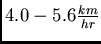 causes an energy increase of
  times the
equivalent energy expenditure to the natural body mass of the torso.
Adding mass to the hands can also cause a significant energy
expenditure. At higher walking speeds and masses greater than
times the
equivalent energy expenditure to the natural body mass of the torso.
Adding mass to the hands can also cause a significant energy
expenditure. At higher walking speeds and masses greater than
 per hand, energy expenditure is approximately twice that of torso
loads [44,202]. However, at loads of
per hand, energy expenditure is approximately twice that of torso
loads [44,202]. However, at loads of  per hand the
effective load was
per hand the
effective load was  times that of torso loads (though the it is
unclear from the data in the tables in [202] how this figure
is derived). These studies suggest that, over a certain mass, arm
carried loads become disproportionately inefficient. However, lighter
loads seem to be inoffensive. Indeed, Symbol reports that their
times that of torso loads (though the it is
unclear from the data in the tables in [202] how this figure
is derived). These studies suggest that, over a certain mass, arm
carried loads become disproportionately inefficient. However, lighter
loads seem to be inoffensive. Indeed, Symbol reports that their
 forearm mounted computer can be used by a wide range of people
engaged in strenuous arm activity for extended periods of time
[221].
forearm mounted computer can be used by a wide range of people
engaged in strenuous arm activity for extended periods of time
[221].
The most efficient means of carrying a 30kg load is by equally distributing the weight between a pack carried on the chest and one on the back. Variations of weight distribution cause slightly more energy expenditure. Surprisingly, carrying the same load on the head is only slightly less efficient, being 1.03X that of the front/backpack [44], or approximately 1.2X that of torso body mass for 14kg loads [202]. Finally, loads carried entirely in a shoulder/backpack are approximately 1.10X less efficient than split in a front/backpack. In some studies, the Borg Scale [110] is used to measure comfort. Generally the sense of comfort is closely related to the effective load figures. However, comfort is noticeably improved in backpacks by using a hollow metal tube frame to minimize contact with the subject's back, encouraging convective cooling.
The placement on the human body of a wearable computer or any consumer electronic depends greatly on its function, expected time of use, and physical characteristics. Recently, Gemperle et al. [74] have studied locations for mounting such devices based on the body's range of motion during typical activities. While this study did not take into account loading characteristics, it found locations otherwise suitable on the hands, head, back, chest, waist, hips, legs, and feet [74]. For light systems, almost any location is adequate from an energy expenditure standpoint, and functional convenience should take precedence.
Mounting the computer on the forearm has many advantages including convenient access, higher availability of turbulent air flow due to the pendulum effect, and heat exchange through the hand. However, as loads increase, a forearm mount becomes impractical. The legs have a similar set of advantages as the arms for heat dissipation with an even larger surface area for interaction. Unfortunately, the legs limit access and have a large penalty for heavier loads. Even so, if the computer hardware can be kept light, power can be readily generated from the user's walking stride. Similarly, feet have the benefit of good air convection and accessibility but have little skin surface area and involve a large effective load. Mounting on the head is efficient even for heavier devices, provides access to many of the user's senses, and has the two heat dissipation advantages of faster natural convective air flow while the user is sedentary and a constant flow of forced air while walking. Unfortunately, hair impedes heat conduction to the skin, and too much bulk on the head can become unwieldy for everyday actions. Mounting the computer on ``core'' body areas such as the torso provides the most efficient load carriage but would result in lesser heat gradients in many instances as the limbs are often colder due to lower ambient conditions. Torso mounts can provide a good platform for sensing but little advantage for harnessing undirected power.
Thus, for heavy systems where environmental conditions are temperate and little heat is generated, placement along the trunk close to the center of gravity is recommended. If these systems also generate significant heat, a frame should be used to limit contact with the body for comfort purposes. Cooler, light systems are only constrained by their size and obtrusiveness and may be mounted close to the hand or foot for power generation considerations. Lighter systems with heat constraints should be placed where air flow or skin contact is available. Thus, in general, the forearms provide a good compromise for consumer and commercial grade wearable computers: good skin conduction, excellent air convection, functional and social accessibility, and moderate loading effects.
The preceding chapters have discussed the issues of heat, power, and load bearing in relation to wearable computer design. These attributes will continue to be of significant importance as wearable computer manufacturers strive for a balance between form factor and function. As technology advances, the amount of processing power and storage will increase per unit of energy and mass. However, there may always be compromises when comparing the abilities of a wearable computer to that of a desktop machine, just as there are compromises currently between a desktop and a mainframe. The important question is when will the capabilities of a wearable computer be sufficient such that the desktop will be relegated to the exotic status of the mainframe in the mind of the consumer?
This thesis describes new applications and modalities for computing that leverage the mobility and close user contact of wearable computers. However, wearable computing, or whatever one wants to call this field of research into intimate man-machine collaboration, is just beginning. The following sections suggest directions for future research.
As stated in the introduction, many of the functions of portable consumer electronics may be subsumed by the wearable computer. An interesting human computer interface question is how can these functions be amplified when used cooperatively? Should music playing software communicate with its diabetic user's blood sugar monitoring program to play energetic music when appropriate? Should a telephone program automatically pause the user's video game for an incoming call? What happens when such cross-interactions become complex, and can they be designed to fail gracefully?
Popular design thinking suggests that interfaces should be specialized physically for their function and be simple enough to be used by anyone after a brief inspection [154]. However, everyday-use wearable computers may allow a different approach, following Alan Kay's suggestion that ``simple things should be simple, complex things should be possible.'' Most devices and their interfaces are instantiated in the physical environment, but wearable computer interfaces exist mainly in the software of the machine and the mental model of the user. A wearable computer, just like most personal computers, provides general functionality that is tailored to particular functions through applications. However, there is a general ``look and feel'' that is shared among the applications. With many desktop systems, this ``look and feel'' may be fully customized by the user, but most users do not have the incentive to learn how to do so since they use the interface for only a couple hours a day.
However, suppose that a user always wears his computer, in the sense that a very near-sighted person always wears his eyeglasses, and all appliances and controls in the user's environment can be accessed through his wearable. Suddenly, the wearable computer can act as an intermediary between the user and the services provided by appliances in the environment, much as the original web browsers acted as intermediaries to information presented on the web with HTML 1.0. The wearable would map any services "discovered" in the user's physical environment to the user's familiar personal environment. The user should have to learn only one, customizable interface, though he may wish to add functionality as more sophisticated wearables become available.
The power and persistence of such an interface would hopefully give users the incentive to customize and streamline the interface to their personal expectations and preferences. In time, children would be raised with computers in their clothing, expecting to manipulate and change the world's interfaces to their wishes. How does this level of empowerment change the use and evolution of everyday devices? How does it change the development of the mind of the user? Would these powers of mutability lead to better designs, exchanged openly between advocates and adapted for local situations, or would user apathy and increasing complexity lead to a standard set of interfaces controlled by a select few? These are open questions that can only begin to be addressed by a combination of environmental and wearable computing in an extensive experiment.
The long-term use of a wearable computer, as suggested by the previous section, implies a tremendous resource: an ongoing record of the human-computer interaction, complete with any sensor data the wearable might record as part of its interface. For example, due to its physical closeness with the user, a wearable may monitor the user's physiological data for health reasons. Similarly, the wearable may record video of its user's hands, looking for gestures used in its interface (i.e. ``draw a square'' or ``record this conversation''). Through examination of a record of its past use and the corresponding contextual environment, the wearable might learn how to streamline its interface or make inferences about the world. For example, if the user always checks his e-mail after lunch, the wearable might associate eating gestures with downloading e-mail from a server. Thus, whenever it sees its user eating, the wearable might automatically download new e-mail, saving the user the download time, or saving the user money by using a slower speed connection. From a previous example, the wearable may learn when and in what manner the user should be interrupted to handle telephone calls or e-mail depending on the user's current task and the perceived importance of the message. In such ways the user's resource, task, and interruption management may be improved. Taking this idea to its extreme, the wearable may learn enough about its user and his everyday environment to act as a temporary surrogate for its user in some situations.
While this thesis demonstrated techniques for creating an augmented reality extension of the World Wide Web, the necessary hardware limited its use to demonstrations. Many questions remain. Where would the information be hosted for each physical area? How would it be organized? What interfaces are appropriate for mobile annotation of the physical world? What are the social ramifications? How should this information be emphasized or filtered based on user context? Everyday life with such systems may create even more drastic changes to the use and access of information than the original World Wide Web.
The anecdotes in Chapter 3 suggest that it is possible to share experiences and information between members of a work group automatically and informally. Unfortunately, the infrastructure was not in place for the automatic updates necessary to maintain such an intellectual collective. What happens when such a system is constantly available? How does it scale with the number of members? How diverse a set of backgrounds can the members have? What modalities can be shared between user experiences? Can video or audio ``memories'' be presented to the user without overwhelming the user's primary task? How will such a system affect traditional education?
While Chapters 7 and 8 introduced the concept of designing wearable hardware that simultaneously uses and assists the human body, the topic remains virtually untouched. How can this concept be used in network design and power distribution [254,11,168]? Can group behavior be exploited [166]? Can interface hardware learn to modify itself based on prior use? How can textiles be exploited for computing [167]?
This thesis has presented both a vision-based architecture and modeling tools for context recovery using wearable computers. It has demonstrated how contextually-aware interfaces might be designed with minimal off-body infrastructure, allowing ease of implementation and protecting user privacy. In addition, issues of power recovery and heat dissipation are explored, presenting novel suggestions for improvements in wearable computing designs. Like any exploration of a new research field, this thesis asks more questions than it answers. Hopefully, though, wearable computing hardware and software will become more common and powerful in the near future, enabling the advanced research suggested in this chapter. Maybe then we will discover how to make man-computer symbioses commonplace.
``The Cyborgs Are Coming'' was intended for Wired magazine, originally written in 1993 at Nicholas Negroponte's suggestion. While Wired never published it, this paper provided a ``wide-eyed'' popular press explanation of why wearable computing is an interesting topic for both industry and academia. Displayed prominently on my office door through 1994 to describe my unofficial project, I eventually made the document a Perceptual Computing technical report (TR#318) when other students and sponsors began to show an interest in wearable computing. To my knowledge, having started my career at the laboratory as an undergraduate in 1989, this document is the first wearable computing paper from the Media Laboratory. More formal technical reports soon followed. ``Affective Computing'' by Rosalind Picard [160] mentions wearable computing as a suitable experimental platform for affective computing. Written for submission to a special issue of the journal Presence on augmented reality, ``Mediated Reality'' by Steve Mann [127] and ``Augmented Reality through Wearable Computing'' by Thad Starner, Steve Mann, Bradley Rhodes, Jeff Levine, Jennifer Healey, Dana Kirsch, Rosalind Picard, and Alex Pentland [213] were listed in the Perceptual Computing technical report series in the Fall of 1995.
Below is the original text of ``The Cyborgs Are Coming'' that was displayed on my office door and handed out at conferences and on the street when someone asked what I was wearing. While sophomoric and now vaguely embarrassing, I include it for historical reasons. The section at the bottom was intended to be included as a side bar to the main article and reflected my experience with pen computers while creating an on-line, cursive handwriting recognizer for Bolt, Beranek, and Newman (BBN).
			The Cyborgs are Coming
				or
	  	      The Real Personal Computers


				by Thad Starner [cyborg@media.mit.edu]
				(submitted to Wired)

	    People look at me strangely when I walk down the street
these days.  However, I'm not particularly surprised; I have a box
strapped to my waist with wires reaching out to my hand and up to my
eye.  I often hold silent conversations with myself, electronically
taking notes on the world around me.  Occasionally one of my
observations triggers electronic memories and gives me new insights.
No wonder people look at me strangely.  You see, I'm one of the
world's first cyborgs.

 	We are on the edge of the next stage of human development: the
combination of man and machine into an organism more powerful than
either.  Almost every user of a computer will be affected in some way:
students, secretaries, lawyers, doctors, scientists, stock brokers,
and CEO's, just to name a few.  While the technology necessary for
this merger may currently look strange, the hardware is obtainable
from today's off-the-shelf components.  For $3000 you can strap on
prototype technology that makes present PDA's (personal digital
assistants) pale in comparison.  In mass production that price could
fall to around $1000.  Currently, the hardware consists of a small,
light graphics display called the Private Eye(R) (the current version is
720x280) that fits over an eye in a pair of sunglasses, a one-handed
chording keyboard (which functions like a full 101-key keyboard), and
a small DOS-based computer which fits on the waist (in my case, the PC
includes 85M of hard drive, 2M of RAM, and several ports including a
PCMCIA).  For a little more money, a cellular phone and modem can be
added (for those net addicts).  While almost plebeian in design, the
combination of these inventions points to a very powerful paradigm in
human-computer interactions.  Furthermore, three multi-billion dollar
product and service areas will be developed by such technology.

			The Vision

	Science fiction has foretold the merging of man and machine
for many years.  Cyborgs with minds partly consisting of silicon
are almost commonplace in today's fiction.  Usually, these characters are
portrayed as the dark side of humanity, dependent on prosthetic neural
circuitry to continue life.  However, some writers have seen these
devices as voluntary additions to the human host, augmenting but not
supplanting the intelligence already there.  This field of
"Intelligence Amplification" (to borrow a term from Vernor Vinge) is
the topic of this article.  While such a term brings visions of direct
brain interfaces, nothing so grandiose (and difficult) will be discussed
here.  Instead, a simpler interface will be described which has
similarly powerful properties of persistence and consistency.

	In recent years, computers have gotten smaller, lighter, and
more powerful while consuming less power.  Fueling this trend is a
great base of users who rationalize a need for computing power while
traveling (or at least while roaming within an organization).  Often
these notebook machines are used for such mundane tasks as "To Do"
lists, appointments, and business contacts.  However, without such
functions the user can be paralyzed.  In fact, the pen-based computer
community is trying to fill the need of the users who find notebook
computers awkward for doing these tasks (unpacking, powering it on,
booting, finding a place to type, etc.).  However, even these machines
are still inconvenient in the real world, for a variety of reasons
that will be examined later.  An ideal interface would be with the
user all the time, listening to the user's real world interactions and
updating appropriate files automatically.  Going even farther, the
computer should monitor the virtual world and notify the user when
appropriate (important e-mail, the value of gold dropping $100.00,
etc.).  While this goal is extremely hard for many reasons, first
level approximations to such man-machine relationships can be made
using relatively simple hardware and software.

			The Private Eye

	Made several years ago, the Private Eye is one of the most
unrecognized revolutions in display technology.  This small, 1 oz.
display uses a single row of 280 LED's and a scanning mirror to
display a screen of 720x280 pixels to the user's eye.  More modern
versions have resolutions of 1024x768 pixels.  The image is crisp, and
the focus can be put anywhere from 10 inches to infinity.  Since the
display is worn close to the eye (for example, in a pair of
sunglasses), the projected image is equivalent to a large screen
display.  Due to the "sharing" effect of the human visual system, the
user can see both the real world and the virtual at the same time
(some variations on this theme use two Private Eyes with half-silvered
mirrors so that stereoscopic cues can be used and both eyes can see
the virtual and the real at the same time).  Furthermore, since there
is no large glass or plastic surface to scratch or bend (the actual
display surface is ~ 1" x 1"), the Private Eye is more robust than
most other portable displays.  The unit is designed to withstand a
three foot drop, and, in my experience, can handle even rougher
treatment.  In fact, the Private Eye would not be too difficult to
ruggedize for use in the military.  Additionally, since the display is
kept near the user's head where humans are much more careful with
respect to impacts, the Private Eye is much less likely to be exposed
to damage than the LCD screens in the stereotypical PDA.

	While this graphics display is not as powerful as the direct
brain connect interfaces described in fiction, the visual system can
process an enormous amount of information and is thus a great primary
interface for receiving data.  In addition, the overlay of graphics on
to the real world allows virtual annotation of real world objects.

	    A Revolutionary User Interface:  The Keyboard?

    So far, keyboards on notebook and pocket computers are either too
large for convenience or too small to use.  This is a direct result
of assuming the standard QWERTY keyboard is good for portable computing.
Manufacturers are afraid that it would take users too long to learn a
new way of typing.  However, beside me is a one-handed chording
keyboard which anyone can be taught to use in 5 minutes.  It is
certainly much easier to learn than the QWERTY interfaces (the letters
actually go in order-"abcdef..."-but are arranged so that speed is not
particularly limited).  In an hour, a beginner can be touch typing.
In a weekend a speed of 10 words/minute can be obtained.  Shortly, 35+
words/minute can be achieved (my personal rate is around 50
words/minute with a macro package).  This is the Twiddler keyboard
from HandyKey (addresses are included at the end of this article).  It
even includes a tilt activated mouse.  The Twiddler is but one of many
one-handed designs out there.  Some designs allow instant access to
both hands if necessary (the Twiddler straps on to one hand).  This
feature may be very desirable in medical fields.  In any case, these
devices allow the use of full-featured keyboards anywhere (including
walking down the street in the rain).  When finished, they can be
stuck in a pocket or left on the belt for easy, instant access.  Not
only are these keyboards convenient, they do not require much CPU
power (unlike handwriting), always correctly recognize a user's input,
and can take an amazing amount of abuse (I have kicked mine into a
door, stepped on it, and gotten it wet, etc.).


			Putting It Together

	When the Private Eye and a one-handed keyboard are combined in
a computer interface, the result overcomes the limitations in
screen-size, access, and user input imposed by many of today's PDA's.
The user can continually see both the real world and the virtual in
his everyday work.  The virtual world can be accessed even while the
user is walking down the street, attending a cocktail party at a
conference, attending a patient, giving a PhD defense, or taking a
quick lunch before going back to Wall Street for more trading.  The
interface is persistent and reliable (due to the simplicity and
packaging of its parts).  Just this beginning system has many
possibilities, and I would like to dwell on these applications as well
as marketability of the current system before moving on.

			Simple Applications

	By adding basic communications through radio or cellular
technology to the base system, many applications present themselves.
As a computer professional, I find the ability to log into my computer
system anywhere, anytime a serious boon.  Even if communications are
not possible for some reason, the ability to edit text and read mail
locally is a major asset.  Computer system administrators could find
such technology invaluable for detecting and fixing employer problems
without having to be physically present.  While such interactions are
possible on a notebook computer, the added portability and the
persistence of this interface allow for better access.  Students can
take notes in class without having to glance down at their screen.
Lawyers can be in communication with their office databases and
support staff while cross-examining a witness.  Repairmen can make
inquiries and orders to the home office without interfering with their
work.  Health care providers can query databases for precedents or
consult a remote physician while examining their patients.  Brokers
could transfer commodities, offer bids, or consult without shouting to
be heard (and, maybe someday, even trade while away from the floor).
Racing enthusiasts could bet and monitor their winnings without being
at the track.  These are but a few of the many applications that are
possible.  In fact, every day I wear my interface people find more
uses for it.

		The Billion Dollar Hardware Business

	While this beginning system may seen clumsy, it is quite
usable.  At first, only a certain breed of technophile or
time-critical information consumer would be interested in looking odd
to gain the power and convenience such an interface would allow (with
the current system, I am often mistaken for a telephone repairman).
However, there are a growing number of individuals out there that
qualify.  In fact, marketing organizations have identified a new
niche: the computer professional.  These individuals use a computer
every day and find it essential to their work.  Furthermore, according
to some estimates, 50% of these individuals earn over $100,000 a year.
Even if the system was just sold as an expensive toy, a market may
exist.  More seriously, due to the unsuitability of handwriting
interfaces for many tasks and the familiar DOS feel to my initial
system, it may usurp the large market the pen manufacturers predict
for their systems.  Customization may leverage the concept into the
service industry (inventory control, quality management, railway
conductors, telemarketers, etc.)  When improvements such as speech
recognition, smaller designs, etc. come along the market will expand
to a broader band of users, much like the notebook market has
(notebook systems are presently outselling desktop models).  Here is a
chance for entirely new computer product lines, with upgrade paths
every two years.  Along with these lines come the necessary support
hardware, such as digital modems and radio gear.

		The Billion Dollar Communications Business

	The Internet, television cable, and cellular telephone all
started as very small systems.  Today these communication mediums are
almost institutions.  Providing cheap and reliable wireless digital
communication technology will become an incredible source of revenue.
Even with just the notebook computer paradigm, many foresee a
tremendous growth.  With the addition of wearable computing (not to
mention intelligence amplification), these figures can only improve
exponentially.  In fact, technology for both long range and very short
range communication will be in high demand, since, after commuting to
work, the user's wearable computer should automatically hook into the
office work environment at higher bandwidths to help the user with
normal chores.  While this may not supplant the need wired interfaces
to a powerful desktop system, the wearable can still help it's user
operate these more powerful machines on a personal level, if only to
separate more casual work (e-mail, weather updates, phone calls on the
wearable) from concentration intensive work (CAD, accounting,
visualization on the desktop).

	Another communications issue is the interfacing of the
different parts of a wearable together.  While the present interface
is wired, it is easy to examine a low power communication system to
wirelessly combine the keyboard, display, and computer.  In fact,
there has been some discussion of using the body itself as the
communications carrier.  According to some initial experiments by
La Monte Yarroll, speeds as high as 1 Mbaud may be possible by driving
a 5V signal across the skin.  More conservative methods may include
infared or low power radio frequency.

		The Billion Dollar Software Business

	While the initial systems may be DOS or Mac based, the new
interface paradigm of persistency allows radical changes in software
design.  The new software should make the user interface simple and
consistent in most situations.  An improved level of user competency
may arise from the increased use of the persistent interface (this is
happening anyways as our children are growing up in a computer
literate world), so these interfaces may become more complex than
ever.  A particular change of software design will be in determining
when to interrupt the user for especially urgent incoming information
or clarification of user input.  The goal is to improve the user's
productivity, not overwhelm his sensors.  The research/software
product field of Intelligent Agents may go far in addressing this
issue.  In fact, an artificial agent will be presented later as a tool
for the author's wearable computer.  This field will exist whether or
not this particular hardware platform is created.  With an increasing
amount of information being generated, intelligent tools will be
necessary in the coming world.
	Furthermore, until communications transponders become
ubiquitous, software will be needed to make the transition from
connected to disconnected use transparent.  Much theoretical and
practical work has gone into such systems already, but the commercial
implementations lag behind.

		The Cyborgs Are Coming:  The New Computing

	One of the simplest, yet most poignant, applications of this
"wearable" technology is augmented memory.  Today, many computer users
already utilize the excellent memories of their computers for storing
phone numbers, addresses, and "to do" lists.  However, many of these
users are then helpless away from their terminals (or have to lug out
their notebooks or, at best, their palmtops, each time they want to
check something).  With durable wearable technology, these users can
check and update their schedules wherever they may be and without
interrupting whoever they may be talking to at the time (especially
useful for storing e-mail addresses at conferences).  In fact,
reminders, meeting agendas, grocery lists, and lecture notes could be
automatically or semi-automatically overlaid on to the real world as
appropriate.  These applications just scratch the surface of what is
possible.

	Wearable computing allows a symbiotic relationship between
computer and human which combines some of the strongest advantages of
both: the creativity and intuition of a human with the precise storage
and searching capacity of the computer.  Suppose, that a reader of
this article has the interface as previously described.  As the reader
scans the text (supposing, for the moment, that this article is in
paper form and not on-line), he types in notes, unanswered questions,
and comments in one window of his word processor.  The reader's
Remembrance Agent (RA) (an intelligent, adaptable piece of software
that specializes to a user's needs) listens to the input and
immediately conducts a search through the user's directories (local
and/or remote) for files with similar contents.  In another window of
the word processor, the RA reports appropriate lines from files
found in its search.  These lines are ranked according to some measure
of "usefulness" that is either directly programmed into the RA or
learned over time.  In this manner, the reader can quickly be reminded of
similar pieces of information obtained in the past.  Through these
small memory assists, the reader can compare two people's views,
confirm statistics, or generate entirely new ideas synthesized from
the foundations laid by others.  Furthermore, the Remembrance Agent
can suggest files for the storage of this article and the reader's
notes on it, possibly improving the reader's organizational skills.
An initial implementation of this software has been completed, and a
more sophisticated and powerful version is underway.

	The implications of such a system are tremendous.  Imagine
college students having immediate access to their education for the
past 20 years, reporters and police detectives who can interactively
and possibly automatically search for clues and leads, stock brokers
whose systems automatically listen to news feeds for information that
might affect prices, scientists with automatic access to a common
storehouse of information which may spur new contacts and discoveries,
CEO's with up-to-the-minute reports on their own and competitor's
companies, lawyers whose Remembrance Agents discover a precedent based
on a new twist in a court room trial, and doctors whose description of
a patient's symptoms finds a match with a rare case reported on the
other side of the world.  The list goes on and on.

	Makers of PDA's have been suggesting similar possibilities for
several years now.  Many have recently toned down their claims.  They
have been duped by the concept of handwriting recognition and toy
scenarios.  Some have underestimated the problems of text retrieval,
user interface, or intelligent agent design.  What makes this scenario
different?  As the next section will show, the intimate, fluid
relationship of man and machine and the large size of the information
databases may change the situation.

	Having a wearable computer makes note paper obsolete.  A
searchable, organized environment where nothing is lost is very
attractive to the users of note paper.  With constant access to a
computer screen and keyboard, the user can store all of his notes for
the day (especially useful for students); take along a textbook,
newspaper, or novel to read on the subway; play a video game; catch up
on e-mail or netnews; debug programming; or compose his next piece of
poetry wherever and whenever he wants.  This is a very strong force
for keeping everything on-line.  Note that this particular interface
reinforces this behavior much more than handwriting based PDA's where
the awkwardness of unpacking, using two hands, and recognition errors
limit the utility of the machine.  Thus, the wearable computer can
expect much more input from the user than more traditional machines.
With this greater input directly from the user, especially over the
period of years, a Remembrance Agent has a much greater likelihood of
being useful.  The Remembrance Agent could easily remind the user of
something he typed several years ago (and subsequently forgot) which
has pertinence to a present problem (even with low recall rates in
unpersonalized text retrieval studies, automated recall is better than
human recall when a database gets large or when the information is
obtained over time).  Furthermore, through this intimate, interactive
relationship with the user, the Remembrance Agent can more easily
learn the user's preferences.  Another advantage is that, if the
interface deals exclusively with plain text, both the hardware and the
software can be upgraded many times without disturbing the knowledge
gained in the past.  However, neither may ever need to be upgraded for
the functionality described.  This would allows a revolutionary
concept in the computer world: a life-long relationship between a user
and a particular machine interface.  As the machine and user adapt to
each other over the years, a new, integrated being might emerge
combining the best features of both.  Imagine a policeman who never
forgets a face (adding a digitizing camera and simple face recognition
software), an architect who never forgets a structure, or a history
teacher who remembers everything he has ever read or been taught.

			Augmented Reality

	Overlaying text on the real world in the augmented memory
applications above can be thought of as a particular subfield in the
realm of Augmented Reality.  Augmented Reality refers to taking the
virtual computer environment and combining it with the real.  Wearable
computing offers a simple, cost effective way to begin experimentation
in this field.  Using Private Eyes to overlay a mono or binocular
image on the real world opens many possibilities.  With the addition
of a tracking system, the user could have a virtual desk overlaid in
three dimensions on his real desk.  Graphical user interfaces could
add physical position to the descriptors of certain files.  For
example, a user could leave files at different locations in the
office.  These could act as reminders for certain actions the user has
to perform.  In addition, such a wearable with tracking might enable
remote conference participants to be overlaid on the real world.
Repairmen might get visual instructions overlaid on the devices they
are supposed to fix.  Architects and interior designers could have
blueprints overlaid on a physical structure as they walk through it (a
longer distance tracker like the Global Positioning System could be
used).  Construction engineers could visualize changes to a structure
in the field.  Doctors could visualize the inside of their patients
before (or while) they operate.  Note that these complicated graphics
might not need to be rendered on the wearable. Instead, a base
computer might be used to calculate the graphics necessary for the
application and then transfer the information to the wearable for
display.  Several research efforts are already underway on these
topics.  However, the registration and tracking tasks necessary in
some of these applications are difficult and may not be overcome in
the near future.

			Knowledge Transfer

	One of the serious issues facing engineering companies today
is the fast turn around of their employees.  Often, by the time the
employee is trained, he is looking for another job.  However, if the
employee used a Remembrance Agent to help keep notes on his training
and work, his replacement can learn a great deal by simply
copying the RA's files.  In this way, the replacement can have access to
a mini-expert for his new job even when the original employee has
left.

	Intelligence Amplification Through Collectives

	Through the coupling of users with wearable interfaces, large
intelligent collectives might form.  The first implementation might be
similar to an Internet irc channel, where several like-minded users
congregate to talk.  Such a channel might be used for real-time
two-way communication from a conference attendee to remote participants who
could not make it in person (possibly with images).  A "help"
channel might also be useful where users listen and answer questions
during spare minutes for the common good (I repeatedly use such an
interface for just this purpose at MIT, tapping into hundreds of other
users).  In this way, the power of a large group can be harnessed
without much organization and without interruption of regular work.
	Another way to harness the power of a group is to allow access
to members' Remembrance Agents.  Thus, if I know that Chris is an
expert on digital signal processing, I can just ask his Remembrance
Agent about convolution without having to trouble Chris directly.
	So far, the collectives described have been loosely coupled
and not personal.  However, a tight collaboration can be formed
between two people by dedicating a portion of each person's screen to
the other's work.  For example, let us imagine such a system between
George and Chris, two computer scientists.  Each time George looks at
a file, the name of the file and the few lines around George's cursor
appear automatically on Chris's screen.  While Chris may not pay
attention to these small disruptions (which are similar to what his
Remembrance Agent may do), he has a constant idea of George's
context.  Next time George and Chris actively talk, Chris can be
easily brought up-to-date on George's work.  Furthermore, if something
George types catches Chris's eye, then Chris can actively give advice
(for example, Chris knows the location of a particular file or command
which George seems to be searching for).  Note that this system can
also be asynchronous and filtered by an agent to avoid sending too
many updates (keystroke by keystroke would be too disruptive) and to
avoid displaying information when the receiving party is asleep.
Simple extensions of this example can be applied to many fields.


			The Here and Now

	Unfortunately, the traditional computer companies have been
ignoring this potential market, and the pen-based companies still hang
on to the myth that handwriting recognition is the correct interface
for PDA's.  However, there are several research companies,
universities, and independent inventors who have discovered wearable
interfaces and have started prototyping the necessary hardware to
become a "cyborg."  Below are some of the companies and individuals
that I have found instrumental in creating my current system and
probably can be tapped to make copies.  A wearable web page is being
developed to provide more information on vendors.

Doug Platt (showed up at the Media Lab with a working prototype when
            mine was still in pieces - my present unit was custom
            made by him and then revamped by me- has several ideas
	    on chording keyboards as well as the unified technology,)
dplatt@cellar.org
Select Tech
(215) 277 4264
1657 The Fairway, Suite 151, Jenkintown, PA 19046

HandyKey Corp.  (the one-handed keyboard/mouse)
(516) 474-4405
141 Mt. Sinai Avenue
Mt. Sinai, NY 11766
handykey@mcimail.com

Private Eye  (display)
Reflection Technology Inc.
230 Second Ave.
Waltham, MA 02154
617-890-5905  FAX 617-890-5918


However, the marketers of the Private Eye are now
Phoenix Group
Plainview, NY (516) 349-1919


Park Engineering  (the main base unit...their general version
		   has a limited speech recognition board built in)
Spokane, Washington
(unfortunately this address has changed)


	As for my personal system, I am slowly evolving a software and
hardware environment I need for everyday use.  I am also working on a
study of the long term effects of using this particular design
(physiological, psychological, and productivity).  Hopefully, as more
wearable users appear (there are about 4 presently), I will be able to
do studies on collaborative work as well.

	Acknowledgements and Disclaimer

	When I first began gathering equipment to experiment with
wearable computing, I thought I was the first.  Of course, this was
wrong.  Many people have worked on these systems both before and after
my personal revelation.  While I try to keep track of everyone who has
influenced my opinions or given me facts to work with, I know that I
can't possibly name them all.  In particular, however, I would like to
thank the following people for equipment, support, ideas, and
criticism during this trek into a new frontier: Russ Hoffman (who
probably started me thinking in this direction with his "silly"
science project back in '86); Devon McCullough; Doug Platt; Steve
Feiner; Pattie Maes; Henry Lieberman; Olin Shivers; Steve Roberts;
Henry Fuchs; Mike Hawley; the folks at HandyKey Corp., Reflection
Technology, and Park Engineering; the participants in
sci.virtual-worlds and comp.sys.pen; and my co-workers at BBN and MIT
who had to suffer through my enthusiastic outbursts and strange
experiments these last few years.

	My opinions are my own.

		Why handwriting-based PDA's won't do it

	Personal Digital Assistants are supposed to be just what their
names imply, personal and assisting.  The PDA manufacturers would have
you believe that you can (or will be able to) take these machines with
you wherever you go, keeping notes, updating schedules, etc.  However,
today's machines have fundamentally bad interfaces for the
following reasons:

	(1)  Small screens.  While the rest of the computer world has
been migrating to larger and larger displays so that the user has
enough room to use GUI's, the screens on PDA's have been getting
smaller and smaller.  Unfortunately, today's PDA's emphasize
portability, which forces the smaller sized screens.  Also, the
handwriting interface most of the PDA's proclaim requires enough room
for the user to write.  This provides a fundamental limit on the
physical size of the screen.

	(2) Awkward.  All the PDA's on the current market require
unzipping, unvelcro-ing, or otherwise unpackaging the PDA when you
want to use it and then repackaging it when you are finished (while
the Newton and the GRID Palmtop are small enough to be attached to
the body, you still have to unvelcro the Newton from your pants or
take out the pen for the Palmtop).  Furthermore, almost all the PDA's
require both hands for use (one to steady the tablet, the
other to write).  This is very inconvenient whenever simple one-line
notes are required.  Also, the user has to be careful to not
damage the large LCD screen (for instance, don't put it in your
back pocket).

	(3)  Handwriting is a bad interface.  The pen-based
manufacturers claim that pen computing provides an intuitive
interface with no training to operate.  However,
handwriting is NOT intuitive.  We spend several years in school
learning how to form our letters properly (some of us never learned).
The pen manufacturers claim that this is still a lowest common
denominator that is taught in the schools, and we can assume users
will know how to write.  However, in today's elementary schools,
children are also being taught how to type.  In fact, some claim
that by the time today's first graders graduate, they will have
typed 40,000 lines of code!  Handwriting is not the wave of the
future, it is the wave of the past.

 	Assume then that handwriting recognition is a temporary
measure (which many manufacturers claim, since speech recognition is
now foreseeable).  However, today's handwriting recognition simply does
not work well.  To get any useful work out of a handwriting system
requires both user and computer training.  So much for the walk-up
interface!  Pen manufacturers claim that this will improve with time,
and indeed it will.  Many research efforts in the area are now
beginning to bear fruit.  However, good handwriting recognition
(writing a cursive paragraph with only one or two recognition
mistakes) still requires most of the processing power of today's top
workstations.  With this amount of power, adequate speech recognition
can be run just as easily!  Why write when you can just talk?

	Even if one ignores the previous two objections to
handwriting recognition, there is still a more basic problem.
Handwriting is just too slow.  Even assuming perfect, immediate
recognition of handwriting, typing is faster for transferring
information from a user to a computer.  Of course, speech recognition
is still faster than either handwriting or typing (in general).

 However, even assuming cheap, fast speech recognition, there will be
times when speech is not convenient (privacy or when already talking
with others).  Even in a speech recognition future, keyboarding will
still be useful by allowing another, possibly parallel, mode of
communication between human and computer.
The instructions for creating a Lizzy wearable computer were first used by the internal MIT community in 1996 and were made public in January of 1997. Josh Weaver contributed the section on constructing a safety glasses mount for the Private Eye based on the author's informal instruction on the subject. Brad Rhodes invented a ``hat-mount'' style of Private Eye use, and the corresponding section below was contributed by him. What follows are Postscript images of the unedited web pages.


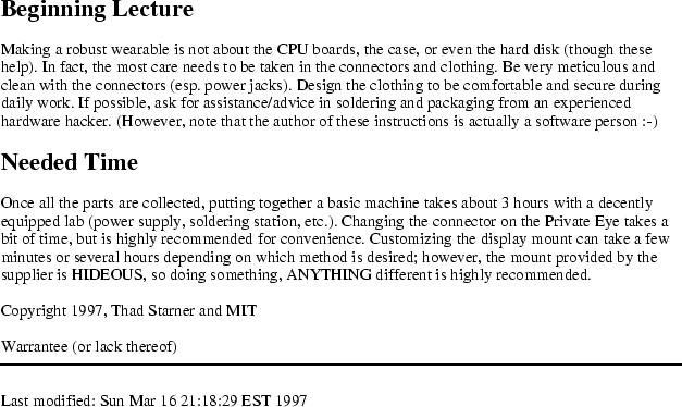
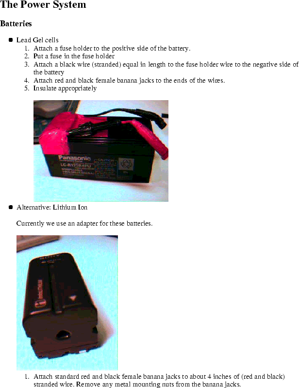
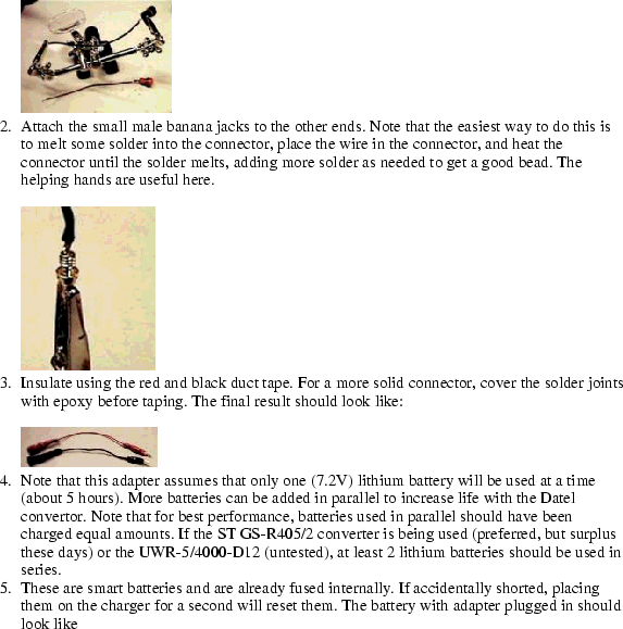
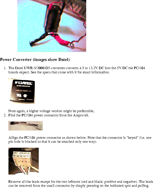
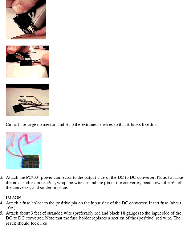
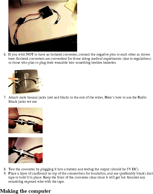
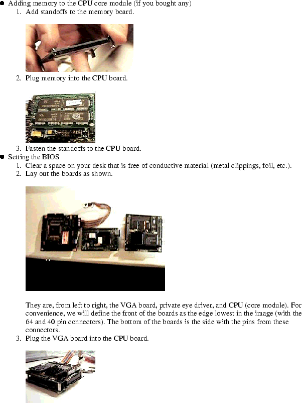
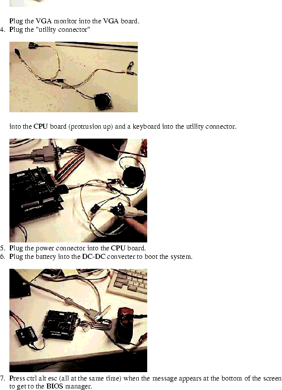
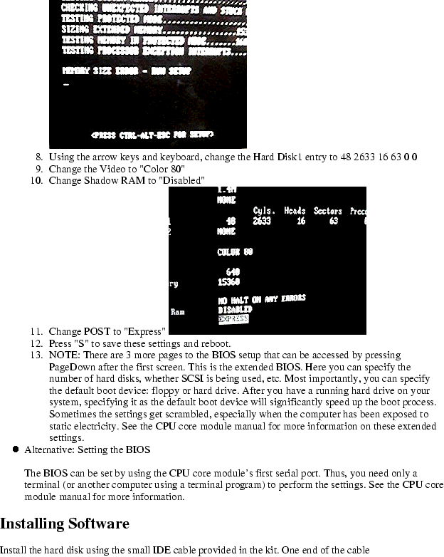
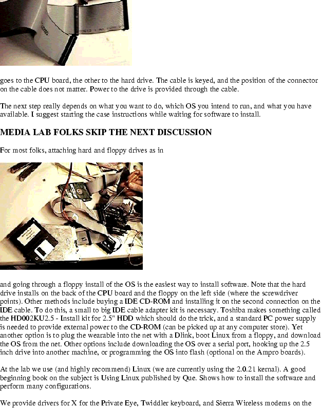
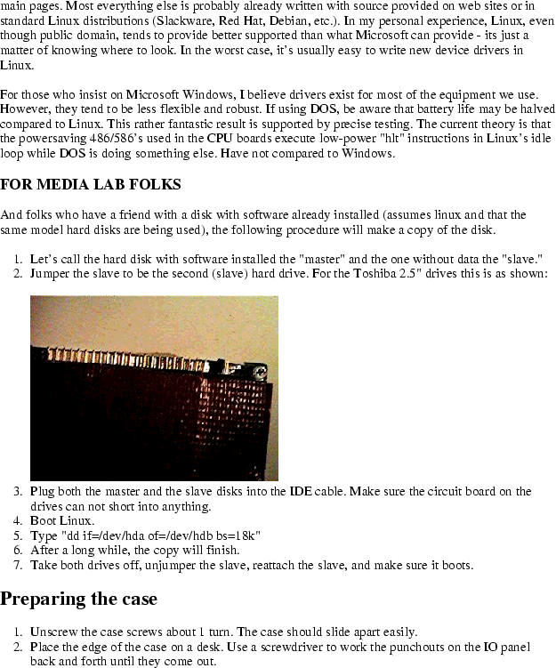
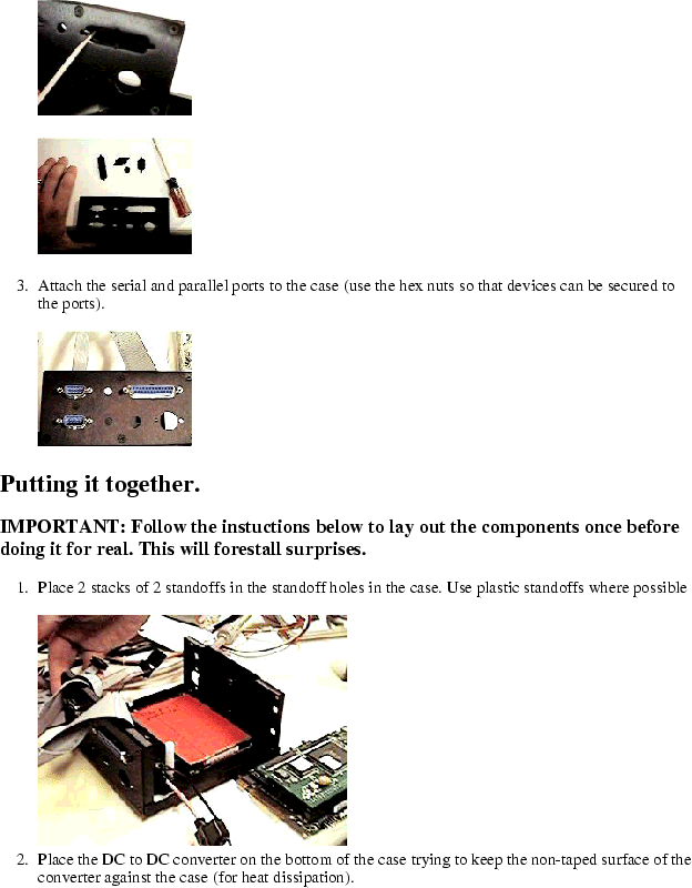
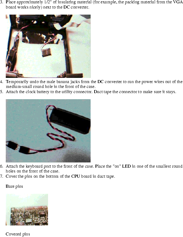
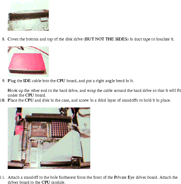
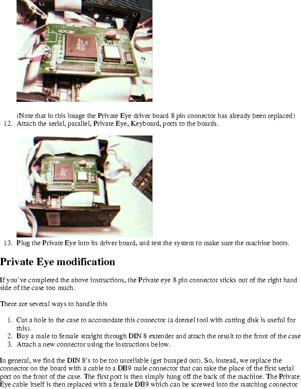
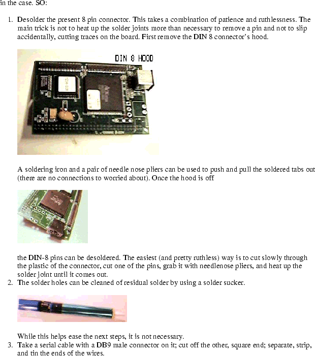
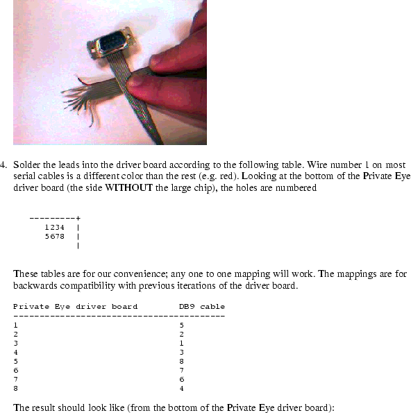
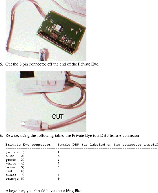
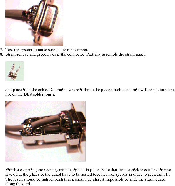
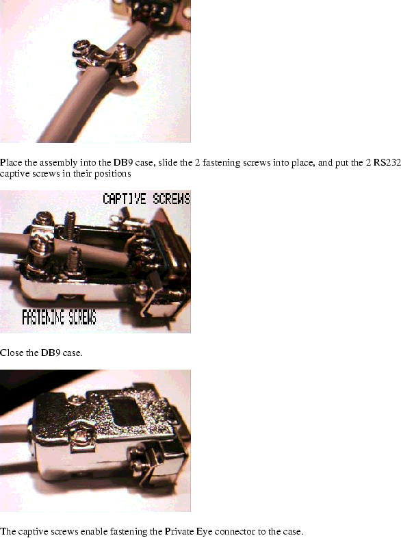
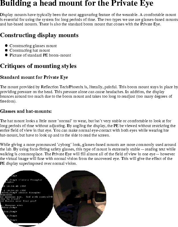
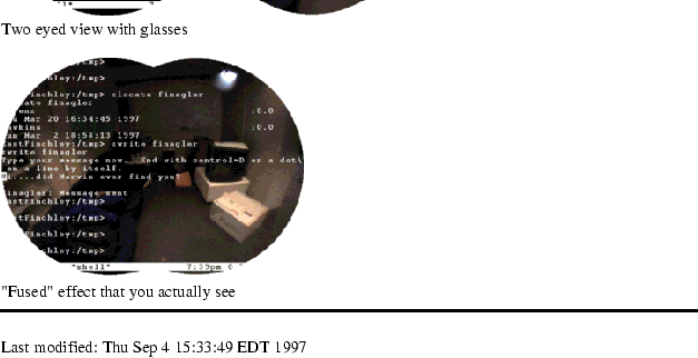
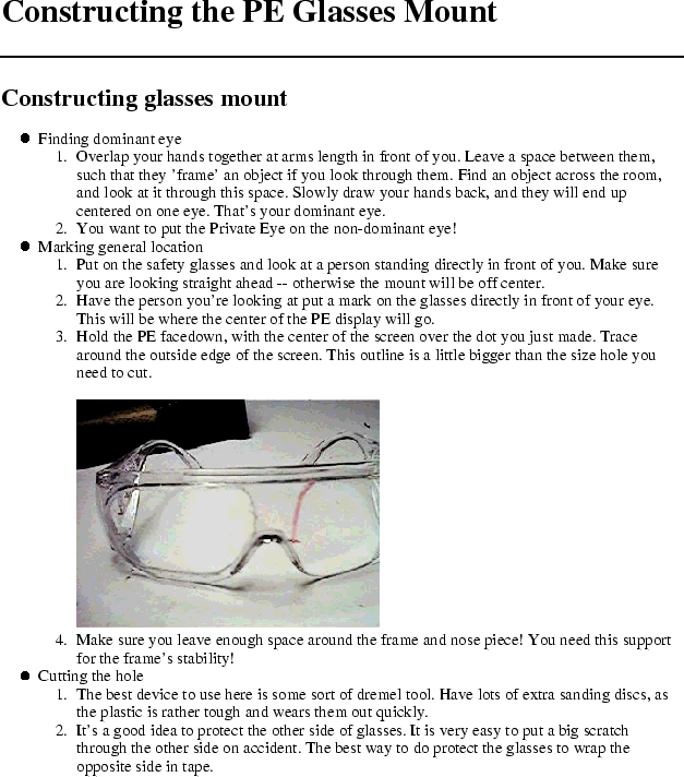
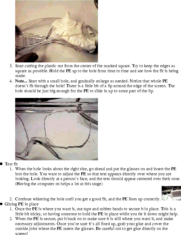
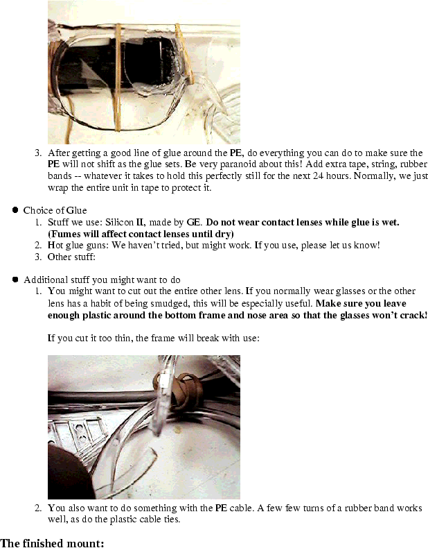
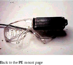
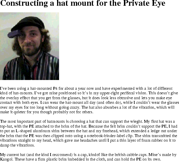
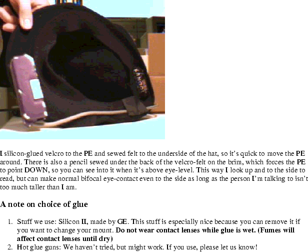
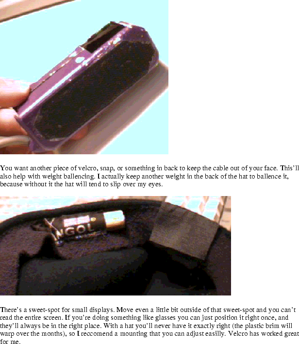


This document was generated using the LaTeX2HTML translator Version 2K.1beta (1.47)
Copyright © 1993, 1994, 1995, 1996,
Nikos Drakos,
Computer Based Learning Unit, University of Leeds.
Copyright © 1997, 1998, 1999,
Ross Moore,
Mathematics Department, Macquarie University, Sydney.
The command line arguments were:
latex2html -split 0 main
The translation was initiated by bob on 2001-07-26

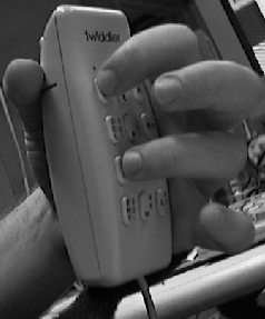
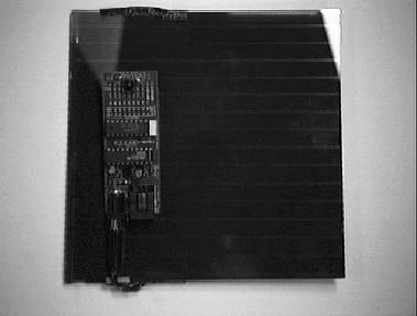
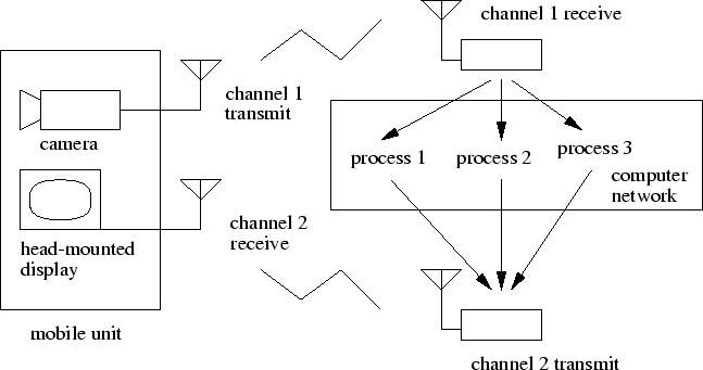
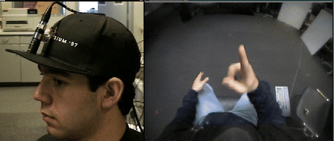
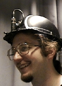
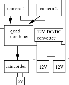
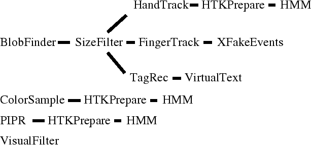
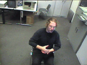
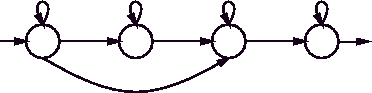
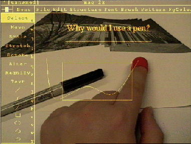
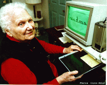
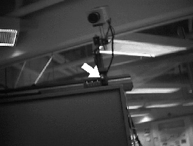
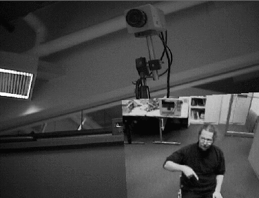
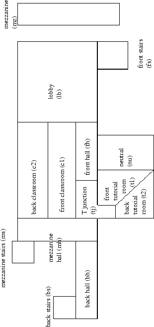
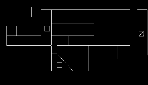
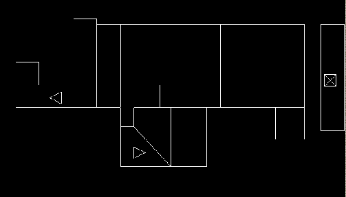
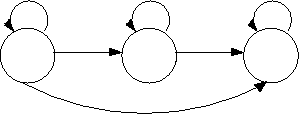
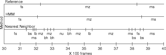
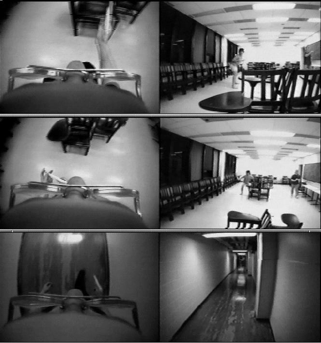


 =20
=20
 =0.35
=0.35 =0.69
=0.69