|
Wasinee Rungsarityotin, Thad E. Starner
College of Computing, GVU Center,
Georgia Institute of
Technology
Atlanta, GA 30332-0280 USA
{wasinee|testarne}@cc.gatech.edu
In this paper we present a framework for a navigation system in an indoor environment using only omnidirectional video. Within a Bayesian framework we seek the appropriate place and image from the training data to describe what we currently see and infer a location. The posterior distribution over the state space conditioned on image similarity is typically not Gaussian. The distribution is represented using sampling and the location is predicted and verified over time using the Condensation algorithm. The system does not require complicated feature detection, but uses a simple metric between two images. Even with low resolution input, the system may achieve accurate results with respect to the training data when given favorable initial conditions.
Recognizing location is a difficult but often essential part of identifying a wearable computer user's context. Location sensing may be used to provide mobility aids for the blind [13], spatially-based notes and memory aids [18,17,8], and automatic position logging for electronic diaries (as used in air quality studies [6]).
A sense of location is also essential in the field of mobile robotics. However, most mobile robots combine extrinsic (environmental) sensors such as cameras or range sensors with their manipulators or feedback systems. For example, by counting the number of revolutions of its drive wheels, a robot maintains a sense of its travel distance and its location based on its last starting point. In addition, many robots can close the control loop in that they can hypothesize about their environment, move themselves or manipulate the environment, and confirm their predictions by observation. If their predictions do not meet their observations, they can attempt to retrace their steps and try again.
Determining location with the facilities available to the wearable computer provides an additional challenge. Accurate, direct feedback sensors such as odometers are unavailable, and many sensors typical in mobile robotics are too bulky to wear. In addition, the wearable has no direct control of the user's manipulators (his/her feet) and consequently is forced to a more loosely coupled feedback mechanism.
In the wearable domain, small video cameras are attractive for sensing because they can be made unobtrusive and provide a great deal of extrinsic information. This is beneficial since we cannot instrument a person with as many sensors as we do a robot. A major challenge of using vision is to build a framework that can handle a complex multi-modal statistical model. A recent approach developed in both statistics and computer vision for problems of this nature is the Condensation algorithm, a form of the Monte Carlo algorithm that simulates a distribution by sampling.
Our approach to determining location is based on a simple geometric method that uses omnidirectional video for both intrinsic (body movement) and extrinsic (environmental changes) sensing. The Condensation algorithm combines these different types of information to predict and verify the location of the user. Inertial data, such as provided by a number of personal dead reckoning modules for the military, can be used to augment or replace the intrinsic sensing provided by the omnidirectional camera. We annotate a two dimensional map (the actual floor plan of the building) to indicate obstacles and track the user's traversal through the building. We attempt to reconstruct a complete path over time, providing continuous position estimates as opposed to detecting landmarks or the entrance or exiting of a room as in previous work.
In the wearable computing community, computer vision has
traditionally been used to detect location through fiducials
[16,14,19,1]. More
recently, an effort has been made to use naturally occurring
features in the context of a museum tour [12].
However, these systems assume that the user is fixating on a
particular object or location and expects visual or auditory
feedback in the form of an augmented reality framework. A more
difficult task is determining user location as the user is moving
through the environment without explicit feedback from the
location system. Starner et al. [20] use
hidden Markov models (HMM's) and simple features from forward and
downward looking hat-mounted cameras (Figure 6)
to determine in which of fourteen rooms a user is traveling with
82% accuracy. Using a forward-looking hat mounted camera, Aoki
et al. [10] demonstrate a dynamic programming
algorithm using color histograms to distinguish between sixteen
video trajectories through a laboratory space with 75%
accuracy. Clarkson and Pentland [5] use HMM's
with both audio and visual features from body-mounted cameras and
microphones for unspecified classification of locations such as
grocery stores and stairways. Continuing this work, Clarkson
et al. [4] use ergodic HMM's to detect the
entering and leaving of an office, kitchen, and communal areas
with approximately 94% accuracy. Unlike these previous systems
which identify discrete events, our system will concentrate on
identifying continuous paths through an environment.
In computer vision, Black [2] and Blake [3] have used the Condensation algorithm to perform activity recognition. In mobile robot navigation, Thrun et al. [7] also use the Condensation algorithm with the brightness of the ceiling as the observation model. A camera is mounted on top of a robot to look at the ceiling, and the brightness measure is a filter response. The most recent work by Ulrich and Nourbakhsh [21] is most similar to ours in that they use omnidirectional video and require no geometric model. However, their goal is to recognize a place on a map, not to recover a path. In this sense, there is no need to propagate the posterior distribution over time and thus their nearest-neighbor algorithm is sufficient.
The first stage in our approach is to capture images of the environment for training. The next stage is labeling of the training data. Because there is no explicit geometric modeling, we need to associate images with positions on an actual blueprint of the environment. The map must also represent obstacles such as walls to assist in the prediction of motion. This is done by the user editing the map to represent obstacles and valid travel areas. In Figure 1, valid areas were painted in gray on the actual blueprint and training paths were traced as series of black dots. We then create a probability model of how likely an image is observed from training paths. We first construct a joint density of the image similarity and distance on a map among training locations and derive the likelihood from the joint density.
We considered two simple image similarity metrics: the L2 norm and a color histogram. We chose the L2 norm because the color histogram did not provide enough discrimination. For example, in our data set, hallways did not have enough color variation to show significant differences in their respective color histograms.
On the other hand, a slight problem with using the L2 norm is maintaining rotational invariance so that different views taken from the same location look similar. We discuss the solution to this problem in Section 2.1.
|
 |
(1) |
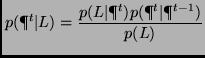
We can assume that the probability of getting a measurement
![]() is constant. Thus, the equation becomes
is constant. Thus, the equation becomes
| (2) |
We greatly benefit from having an omnidirectional camera because
it allows us to use a normalized ![]() distance as a similarity
metric. Assuming that changes caused by translation are
negligible, we only need to make the
distance as a similarity
metric. Assuming that changes caused by translation are
negligible, we only need to make the ![]() metric invariant to
rotation. We do this by incrementally rotating the image until we
find a minimum error. This can be viewed as an image
stabilization process.
metric invariant to
rotation. We do this by incrementally rotating the image until we
find a minimum error. This can be viewed as an image
stabilization process.
Using the same definition for a state and observation, define the
likelihood
![]() , where
, where ![]() is a predicted position at time
is a predicted position at time ![]() ,
,
![]() the normalized
the normalized ![]() norm,
norm,
![]() ,
and
,
and ![]() is a state in the training data nearest to
is a state in the training data nearest to
![]() . The next section will explain an experiment on
finding the likelihood for the localization system. We will focus
on modeling a case when the state (user's location) is near a
training path (having distance on a map less than 10 pixels (3
feet per pixel) away).
. The next section will explain an experiment on
finding the likelihood for the localization system. We will focus
on modeling a case when the state (user's location) is near a
training path (having distance on a map less than 10 pixels (3
feet per pixel) away).
|
|
As seen in Figure 2, the likelihood is far from
being a simple two dimensional function. Although the
distribution appears noisy, it exhibits some structure as seen in
the contour plot. Rather than performing a full minimization to
solve for a closed form, we have chosen to estimate the
likelihood with a combination of known distributions. To estimate
the likelihood, first we compute a non-parametric form of the
joint distribution ![]() by uniform bin-size and it follows
that
by uniform bin-size and it follows
that
![]() . Looking at a plot of
. Looking at a plot of
![]() in Figure 2(a), we have observed
that if the image distance
in Figure 2(a), we have observed
that if the image distance ![]() is higher than 0.1, it is
likely that the state is not a good match. We have used 0.1 as
the standard deviation for the normal distribution and our
experiment in Section 3.1 confirms that the above
observation is reasonable.
is higher than 0.1, it is
likely that the state is not a good match. We have used 0.1 as
the standard deviation for the normal distribution and our
experiment in Section 3.1 confirms that the above
observation is reasonable.
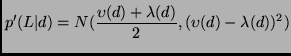
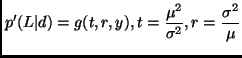
In summary, we have tried three different functions to
approximates the likelihood. Define the lower and upper limit of
![]() in Figure 3 as
in Figure 3 as
![]() and
and
![]() .
.
Let
![]() be a parametric estimation of
be a parametric estimation of ![]() . We
can define our three choices in terms of
. We
can define our three choices in terms of
![]() as:
as:
We tried two motion models. One was a dynamic model with position and velocity as random variables having Normal distributions. The second model was a simplified motion model of the parabolic camera. Without a high resolution input, a full recovery of ego-motion is a difficult problem even with an omnidirectional camera. Most of the algorithms presented in computer vision require good features to track. Given a low resolution imaging system such as ours (6), finding good features can be expensive.
To derive the simplified camera model, we took the same approach
by Yagi et al. [22] with the assumption that the
camera moves in a horizontal plane with constant height above the
ground. We simplified the model more by only computing the motion
of the ground-plane. The model has three degrees of freedom,
translation ![]() and rotation
and rotation ![]() around the Z-axis.
Because we only account for the motion of the ground-plane,
motion in other planes will contain more error. To represent the
uncertainty of the estimated motion, we distributed a set of
samples around the solution and applied it to the Condensation
algorithm. A random variable
around the Z-axis.
Because we only account for the motion of the ground-plane,
motion in other planes will contain more error. To represent the
uncertainty of the estimated motion, we distributed a set of
samples around the solution and applied it to the Condensation
algorithm. A random variable
![]() was then
transformed into a two dimensional space to be rendered on a map
by rotating the translation vector
was then
transformed into a two dimensional space to be rendered on a map
by rotating the translation vector ![]() by the angle
by the angle
![]() .
.
Although we only mention estimating a person's displacement from a camera, the framework is not restricted to a single motion model. We could replace the recovery of the ego-motion with the inertial sensor or combine both. For our experiments, we only tried to estimate from the camera because we have a better way to quantify the uncertainty.
The Condensation algorithm provides a framework that propagates the density over time and works with multimodal distributions that can be represented as sets of samples. In other words, the Condensation algorithm can be applied to a tracking problem where distributions of tracking parameters are not unimodal- unimodal distribution is visualized as having exactly one peak (not a ridge) such as the Normal distribution.
We give a summary of the algorithm below. For more information, [3] and [11] give an excellent overview of the method. Related algorithms are Importance Sampling [3,11] and Markov Chain Monte Carlo methods (MCMC) [15,7]. A review by Neal [15] provides a comprehensive review with attention to their applications to problems in artificial intelligence.
Initial conditions for navigation can be determined by defining
the prior density ![]() . Alternatively, it is possible to
allow the initial condition to approach a steady state in the
absence of initial measurements. Provided that a unique solution
exists and the algorithm can converge fast enough, we can
populate an entire map with samples and let the Condensation algorithm
[7] converges to the expected solution.
For all of our experiments, an initial position
. Alternatively, it is possible to
allow the initial condition to approach a steady state in the
absence of initial measurements. Provided that a unique solution
exists and the algorithm can converge fast enough, we can
populate an entire map with samples and let the Condensation algorithm
[7] converges to the expected solution.
For all of our experiments, an initial position ![]() is manually specified by looking at the test sequence. In this
case, we use a Gaussian for
is manually specified by looking at the test sequence. In this
case, we use a Gaussian for ![]() and thus direct sampling
can easily be used. We can use a similar scheme to recover from
getting lost-this is the same as finding a new starting
point. Deciding that we are lost can be done by observing the expected
distance from the training path or the expected weight assigned
to samples. Decision regions for the confidence measure can be learned
from the likelihood function. Empirically, we make a plot for both parameters and
define a confidence region for being certain, uncertain, or
confused. In Section 3.2, we will discuss how
we define these decision regions from experimental results.
and thus direct sampling
can easily be used. We can use a similar scheme to recover from
getting lost-this is the same as finding a new starting
point. Deciding that we are lost can be done by observing the expected
distance from the training path or the expected weight assigned
to samples. Decision regions for the confidence measure can be learned
from the likelihood function. Empirically, we make a plot for both parameters and
define a confidence region for being certain, uncertain, or
confused. In Section 3.2, we will discuss how
we define these decision regions from experimental results.
|
For the training data, the results show that estimating ![]() with exponential fall off gives the best result (Figure
2. This finding shows that if the similarity
measure was high (low image difference), a new sequence would
follow a training path and hence we can use the training data as
the ground truth. For our data set, this prior was so strong that
the exponential decay independent of
with exponential fall off gives the best result (Figure
2. This finding shows that if the similarity
measure was high (low image difference), a new sequence would
follow a training path and hence we can use the training data as
the ground truth. For our data set, this prior was so strong that
the exponential decay independent of ![]() worked well. This
explained why the first choice, Equation 3
performed better than the rest. For other data sets, Equations
4 or 5 may work better. In summary,
we approximate by choosing a parametric function that appears
similar to the actual likelihood. A better way to learn the
likelihood is to estimate a mixture of Gaussian or Gamma
distributions.
worked well. This
explained why the first choice, Equation 3
performed better than the rest. For other data sets, Equations
4 or 5 may work better. In summary,
we approximate by choosing a parametric function that appears
similar to the actual likelihood. A better way to learn the
likelihood is to estimate a mixture of Gaussian or Gamma
distributions.
|
For experimental verification, we labeled all the test sequences to provide the ground truth. We randomly picked a starting position to avoid bias. We ignored the recovery problem by avoiding an area which we have not seen before. Two motion models were used: a simple random walk and the ego-motion of a camera. Examples of images taken from our omnidirectional parabolic camera are shown in Figure 6. We then masked out some visual artifacts caused by the ceiling, the camera and the wearer (Figure 6).
|
Table 1 summarizes the performance of our localization system running on one hundred cross-validation tests. A cross-validation is based on two different sequences of images taken from the same path, but acquired at different times. One of the sequences is used as training, while the other is used as test data. We generated a hundred test sequences by choosing one hundred segments from a nine-minute sequence. For each test, the starting position is known and the system tracks for one minute. Results from the simulation are samples weighted by the posterior distribution at each time step. They are shown as clouds of points propagating over time in Figure 4. Small clouds of samples indicate higher confidence.
For each test, the standard deviation of the likelihood model was 0.1 for the reason given in Section 3.1. We needed to capture at 30 Hz to recover the camera ego-motion, but the likelihood was only computed every sixth frame to increase efficiency. The task of the localization system is to keep track of a person's location and report a confidence measure. After one iteration of the algorithm, it reported a confidence measure as a cumulative weight of all samples. By observing the weight reported by the system, we defined three confidence types as confident, uncertain, or confused. Being uncertain means that a system has competing hypotheses. This results in one or more clouds of samples; in this case, the expected location may lie in a wall between two areas. Being lost implied that the system encountered a novel area or the likelihood was not giving enough useful information. In this case, the prediction was no longer useful. Although it may be possible to recover if a good match appears at a later time, no recovery method was implemented. One possible recovery method is to distribute samples over the entire map to find better candidates to continue tracking.
|
If the total reported weight was less than 200, we classified the system as being confident, from 200 to 800 as being uncertain, and beyond 800 being confused. For both tests with the random walk and motion estimation, the system was confident for 30% of the time, uncertain for 40% and confused for 29.5% (Table 1). With motion estimation, the error rate was improved for the uncertain case because additional knowledge was provided as to which hypotheses to choose. To show that our confidence measure was meaningful, we associated the measure with a deviation from the true path. If a deviation is more than 30 pixels from the actual path, then this is an error. The error rates were then reported for three confidence measures. As shown in the Table 1, when the system is very confident, the error rate is low. Two tests were performed to study if a motion estimation could reduce the uncertainty. While it did reduce the uncertainty, our simplified motion model introduced more noise to the system which results in an increase in the error rate even though the system is confident. More than anything, the high uncertainty and confusion is mainly contributed from having a sparse training set.
It took about three hours to complete a simulation of one hundred test sequences that added up to 100 minutes in real time. Thus, we expect an update rate for an on-line system to be about 2 Hz. With the current system, the most time consuming part for every sample is finding the nearest state from the training set. This can be greatly improved by using an adaptive representation of a 2D map such as an adaptive quad-tree or a Voronoi diagram.
On video recordings of real situations in an unmodified environment, we have demonstrated that our system can continuously track independent test sequences 95% of the time given a favorable starting location. The results show that a robust localization system will need a better motion model.
Future work should concentrate on combining intrinsic information from the camera with the inertia data and improving the statistical model of the observation to include multiple views. Starner et al. [20] use simple image measurement from forward and downward looking views as shown in the top row, while our system considers only the omnidirectional view. Measurements from all views can be combined through the observation model. Future implementations can also use the confidence measure to remain noncommittal and explore the solution space for a good location to restart the Condensation algorithm. Using this information allows the system to recover from situations where sufficient data to match does not exist. To handle changing environment we can extend Condensation to track time. We simply record the time that our training samples are taken. Since we know that the time of day cannot change drastically from one room to another, the local context affects of condensation and the comparison function still apply. Thus, time is simply another dimension that can vary as the algorithm walks through the building. A side result is not only does the system tell you where you are, but could also give an estimate on the time of day.
This document was generated using the LaTeX2HTML translator Version 2K.1beta (1.47)
Copyright © 1993, 1994, 1995, 1996,
Nikos Drakos,
Computer Based Learning Unit, University of Leeds.
Copyright © 1997, 1998, 1999,
Ross Moore,
Mathematics Department, Macquarie University, Sydney.
The command line arguments were:
latex2html -split 0 location
The translation was initiated by bob on 2001-07-30
![\includegraphics[width=3.0in]{floormap.eps}](img8.png)
![\includegraphics[width=3.0in]{trainingpath.eps}](img9.png)
![\includegraphics[width=3.0in]{density3D.ps}](img24.png)
![\includegraphics[width=2.2in]{allgauss.ps}](img25.png)
![\includegraphics[width=2.0in]{estGauss.ps}](img26.png)
![\includegraphics[width=2.2in]{gammlikeli.ps}](img27.png)
![\includegraphics[width=3.0in]{contour.ps}](img28.png)
![\includegraphics[width=1.7in]{limits.ps}](img29.png)
![\includegraphics[width=1.5in]{samples112.eps}](img69.png)
![\includegraphics[width=1.5in]{samples118.eps}](img70.png)
![\includegraphics[width=1.5in]{samples124.eps}](img71.png)
![\includegraphics[width=1.5in]{samples128.eps}](img72.png)
![\includegraphics[width=1.5in]{samples132.eps}](img73.png)
![\includegraphics[width=1.5in]{samples136.eps}](img74.png)
![\includegraphics[width=1.5in]{samples140.eps}](img75.png)
![\includegraphics[width=1.5in]{samples147.eps}](img76.png)
![\includegraphics[width=2.5in]{confidence.eps}](img80.png)
![\includegraphics[width=2.7in]{confidenceContour.eps}](img81.png)
![\includegraphics[width=1.0in]{bright_pano0.eps}](img82.png)
![\includegraphics[width=1.0in]{bright_pano1.eps}](img83.png)
![\includegraphics[width=1.0in]{bright_pano4.eps}](img84.png)
![\includegraphics[width=1.0in]{dark_pano0.eps}](img85.png)
![\includegraphics[width=1.0in]{dark_pano1.eps}](img86.png)
![\includegraphics[width=1.0in]{dark_pano2.eps}](img87.png)
![\includegraphics[width=1.0in]{pano_mask.eps}](img88.png)
![\includegraphics[width=1.2in]{allviews.eps}](img89.png)